Image

Servicing The ‘Not Serviceable’ Bearings On A Vacuum Power Head

ImageEveryone knows that bearings are a consumable wear item, and that the power head of a vacuum likely contains bearings that will eventually need to be replaced. Yet when the manufacturer wants you to toss out the entire roller and pay $80 for the privilege, that feels rather steep and unnecessary. In the case of [Mark Furneaux], the roller in the power head of his Filter Queen brand vacuum felt particularly over the top to toss, since it’s all fancy wood with very durable brushes.

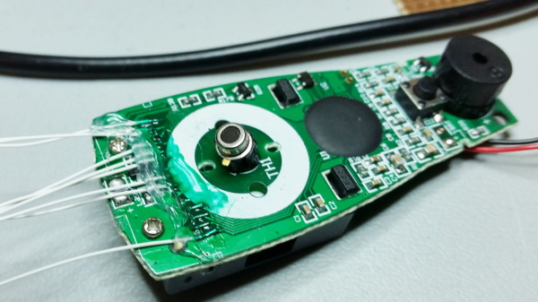
One of the bearings had stopped being a bearing, resulting in the plastic that held it in place beginning to melt. Fortunately the damage hadn’t progressed to the point where printing a replacement was necessary, so instead it was time to figure out how to remove the bearings without permanent damage. The trick that the manufacturer used was to peen the ends of the metal shafts that the bearings fit onto, requiring some Dremel action to convince them to come off.

After some careful modifications like this, the remnants of the old bearings came off and their replacements could go on. Due to the metal shaft modifications, it is now mostly the plastic caps on either end which grip the bearings, but it seems to work well enough. For $2 in bearings and some labor on [Mark]’s end, he managed to keep a perfectly good roller brush out of the landfill, and future bearing replacements should be much easier.

Continue reading “Servicing The ‘Not Serviceable’ Bearings On A Vacuum Power Head”

Image

Performing A Chip Transplant To Resurrect A Dead Board

[Uri Shaked] accidentally touched a GPIO pin on his 3.3 V board with a 12 V alligator clip, frying the board. Sound familiar? A replacement would have cost $60, which for him wasn’t cheap. Also, he needed it for an upcoming conference so time was of the essence. His only option was to try to fix it, which in the end involved a delicate chip transplant.

Removing the shield on the Bluetooth LE board
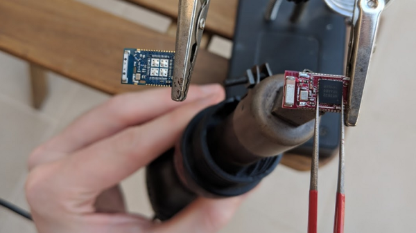
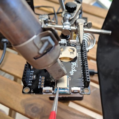
The board was the Pixl.js, an LCD board with the nRF52832 SoC with its ARM Cortex M4, RAM, flash, and Bluetooth LE. It also has a pre-installed Espruino JavaScript interpreter and of course the GPIO pins through which the damage was done.

Fortunately, he had the good instinct to feel the metal shield over the nRF52832 immediately after the event. It was hot. Applying 3.3 V to the board now also heated up the chip, confirming for him that the chip was short-circuiting. All he had to do was replace it.

Digging around, he found another nRF52832 on a different board. To our surprise, transplanting it and getting the board up and running again took only an hour, including the time to document it. If that sounds simple, it was only in the way that a skilled person makes something seem simple. It included plenty of delicate heat gun work, some soldering iron microsurgery, and persistence with a JLink debugger. But we’ll leave the details of the operation and its complications to his blog. You can see one of the steps in the video below.

It’s no surprise that [Uri] was able to dig up another board with the same nRF52832 chip. It’s a popular SoC, being used in tiny, pocket-sized robots, conference badges, and the Primo Core board along with a variety of other sensors.

Continue reading “Performing A Chip Transplant To Resurrect A Dead Board”

Image

Reading An IR Thermometer The Hard Way

[Derryn Harvie] from the MakeHackVoid maker space hacked a $10 IR Thermometer and made it talk USB. Sounds easy? Read on.

He opened it up in the hope of finding, and tapping into, a serial bus. But he couldn’t find one, and the main controller was a COB blob – hidden under unmarked black epoxy. Normally this is a dead-end.  (We’ve seen some interesting approaches to decapping epoxy blobs, and even ICs with lasers.)

But [Derryn] went his own way – intercepting the data going from the micro-controller to the LCD display, and reverse engineering it using another microcontroller. He scraped off the solder mask over the tracks leading to the LCD display, and used an oscilloscope to identify the common drive lines. He then used a function generator to excite each of the LCD common lines and the segments lines to build a complete matrix identifying all the combinations that drove the segments. With all the information decoded, wires were soldered so he could hook up an Arduino, and the cut tracks repaired.

Since the LCD was a multiplexed display, the bias voltages were at four levels. Luckily, he could extract most of the LCD information by reading just eight of the segment drive lines, using up all of the analog inputs on the Arduino. Perhaps a different microcontroller with more ADC inputs would have allowed him to display more LCD functions. Well, he can always upgrade his upgrade later. If you have a similar hack to implement, then [Derryn]’s code could be useful to get started.

Thanks, [csirac2] for sending us this tip from MakeHackVoid.