<?xml version="1.0" encoding="utf-8"?>
<feed xmlns="http://www.w3.org/2005/Atom" xmlns:media="http://search.yahoo.com/mrss/">
    <title>Karl D.D. Willis</title>
    <link href="https://karlddwillis.com/feed.xml" rel="self" />
    <link href="https://karlddwillis.com" />
    <updated>2025-10-08T10:17:39-07:00</updated>
    <author>
        <name>Karl D.D. Willis</name>
    </author>
    <id>https://karlddwillis.com</id>

    <entry>
        <title>AutoConstrain in Fusion</title>
        <author>
            <name>Karl D.D. Willis</name>
        </author>
        <link href="https://karlddwillis.com/autoconstrain-in-fusion/"/>
        <id>https://karlddwillis.com/autoconstrain-in-fusion/</id>
        <media:content url="https://karlddwillis.com/media/posts/38/AutoConstrain-Fusion.jpg" medium="image" />
            <category term="Product"/>

        <updated>2025-04-02T14:58:08-07:00</updated>
            <summary type="html">
                <![CDATA[
                        <img src="https://karlddwillis.com/media/posts/38/AutoConstrain-Fusion.jpg" alt="" />
                    AutoConstrain is a new feature in Autodesk Fusion that uses machine learning&hellip;
                ]]>
            </summary>
        <content type="html">
            <![CDATA[
                    <p><img src="https://karlddwillis.com/media/posts/38/AutoConstrain-Fusion.jpg" class="type:primaryImage" alt="" /></p>
                <p class="" data-start="233" data-end="593"><em>AutoConstrain</em> is a new feature in Autodesk Fusion that uses machine learning to automatically infer and apply geometric constraints to engineering sketches. It helps transform loosely drawn 2D geometry into well-defined, parametric designs, automatically detecting relationships like horizontal, vertical, tangent, and equal.</p>
<p data-start="233" data-end="593"><div class="post__iframe"><iframe loading="lazy" width="665" height="374" src="https://www.youtube.com/embed/SBmDZuFTIAo?si=81dIXogMVpzhUFd5" title="YouTube video player" frameborder="0" allow="accelerometer; autoplay; clipboard-write; encrypted-media; gyroscope; picture-in-picture; web-share" referrerpolicy="strict-origin-when-cross-origin" allowfullscreen="allowfullscreen"></iframe></div>
<p class="" data-start="595" data-end="894">This capability is powered by a deep learning model trained on 2D geometry to predict constraints and dimensions that maintain design intent. By analyzing the structure and layout of sketch entities, the model suggests constraints that not only make sense mathematically, but also align with how designers typically work.</p>
<h3 data-start="595" data-end="894">Why AutoConstrain?</h3>
<p class="" data-start="925" data-end="1206">Sketch constraints are foundational to parametric design. They define how geometry behaves when modified and are critical to ensuring models are predictable and editable. But today, adding constraints is largely a painstaking manual process and often overlooked until things break.</p>
<figure class="post__image"><img loading="lazy"  src="https://karlddwillis.com/media/posts/38//AutoConstrain-DesignIntent.png" alt="" width="1862" height="937" sizes="(max-width: 1024px) 100vw, 1024px" srcset="https://karlddwillis.com/media/posts/38//responsive/AutoConstrain-DesignIntent-xs.png 300w ,https://karlddwillis.com/media/posts/38//responsive/AutoConstrain-DesignIntent-sm.png 480w ,https://karlddwillis.com/media/posts/38//responsive/AutoConstrain-DesignIntent-md.png 768w ,https://karlddwillis.com/media/posts/38//responsive/AutoConstrain-DesignIntent-lg.png 1024w"></figure>
<p class="" data-start="1208" data-end="1495">In real workflows, designers either spend time adding constraints by hand or leave sketches underconstrained, leading to unintended behaviors during editing. As shown above, changing a dimension from 100 mm to 60 mm in an underconstrained sketch (top) distorts the design, breaking its symmetry. With proper constraints (bottom), the geometry adjusts predictably, preserving the intended relationships. With AutoConstrain, we set out to build a system that understands sketches the way a designer does, not just as lines and arcs, but as meaningful arrangements that imply design intent.</p>
<h3 data-start="1208" data-end="1495">Learning to Constrain</h3>
<p data-start="1208" data-end="1495">At the core of AutoConstrain is a deep learning model that takes an engineering sketch as input and predicts a sequence of dimensions and constraints that reference the geometric primitives in the sketch. The sketch below shows how different constraints and dimensions reference sketch primitives. Tangent constraints (blue) reference a line and an arc, horizontal constraints (orange) reference two lines, and linear dimensions (red) reference two points.</p>
<figure class="post__image"><img loading="lazy"  src="https://karlddwillis.com/media/posts/38/AutoConstrain-ConstraintsDimensions.png" alt="" width="2000" height="1057" sizes="(max-width: 1024px) 100vw, 1024px" srcset="https://karlddwillis.com/media/posts/38/responsive/AutoConstrain-ConstraintsDimensions-xs.png 300w ,https://karlddwillis.com/media/posts/38/responsive/AutoConstrain-ConstraintsDimensions-sm.png 480w ,https://karlddwillis.com/media/posts/38/responsive/AutoConstrain-ConstraintsDimensions-md.png 768w ,https://karlddwillis.com/media/posts/38/responsive/AutoConstrain-ConstraintsDimensions-lg.png 1024w"></figure>
<p>As the AutoConstrain model must dynamically reference geometry within each sketch, we combine a Transformer decoder with a pointer network architecture. This allows the model to "point" to the relevant sketch elements during generation. The figure below shows how sketch primitives are provided as input and the output is a sequence of predicted constraints/dimensions that reference back to the sketch primitives.</p>
<figure class="post__image"><img loading="lazy"  src="https://karlddwillis.com/media/posts/38/AutoConstrain-Sequence.png" alt="" width="2000" height="643" sizes="(max-width: 1024px) 100vw, 1024px" srcset="https://karlddwillis.com/media/posts/38/responsive/AutoConstrain-Sequence-xs.png 300w ,https://karlddwillis.com/media/posts/38/responsive/AutoConstrain-Sequence-sm.png 480w ,https://karlddwillis.com/media/posts/38/responsive/AutoConstrain-Sequence-md.png 768w ,https://karlddwillis.com/media/posts/38/responsive/AutoConstrain-Sequence-lg.png 1024w"></figure>
<p>To train the model we randomly remove constraints and dimensions, and task the model with predicting the missing elements. This allows the model to learn to complete partially constrained sketches in a way that is consistent with existing geometry and design intent.</p>
<figure class="post__image"><img loading="lazy"  src="https://karlddwillis.com/media/posts/38/AutoConstrain-TrainingData.png" alt="" width="2212" height="1462" sizes="(max-width: 1024px) 100vw, 1024px" srcset="https://karlddwillis.com/media/posts/38/responsive/AutoConstrain-TrainingData-xs.png 300w ,https://karlddwillis.com/media/posts/38/responsive/AutoConstrain-TrainingData-sm.png 480w ,https://karlddwillis.com/media/posts/38/responsive/AutoConstrain-TrainingData-md.png 768w ,https://karlddwillis.com/media/posts/38/responsive/AutoConstrain-TrainingData-lg.png 1024w"></figure>
<p>To further improve results, we fine-tune the model on fully constrained sketches and apply <em>Classifier-Free Guidance, </em>a technique that biases the model toward generating complete, well-constrained outputs. These strategies improve the quality and usability of AutoConstrain.</p>
<h3 class="" data-start="3688" data-end="3718">Deep Collaboration</h3>
<p class="" data-start="3720" data-end="4149">AutoConstrain is the result of deep collaboration across Autodesk’s research, product, and ML platform teams. As head of the Model Operations team, I helped guide the development of this feature from early-stage experimentation to production deployment. Our team focuses on operationalizing foundation models across Autodesk’s product portfolio, ensuring reliability, performance, and seamless integration into tools like Fusion. This project reflects the kind of AI we aspire to build at Autodesk: intelligent, intuitive, and embedded directly into the creative process to help users focus on what matters most—design.</p>
<p class="" data-start="4755" data-end="4775"><strong data-start="4755" data-end="4775">Further Reading:</strong></p>
<ul data-start="4777" data-end="5113">
<li class="" data-start="4777" data-end="4950">
<p class="" data-start="4779" data-end="4950"><a data-start="4779" data-end="4950" rel="noopener" target="_new" class="" href="https://www.research.autodesk.com/blog/using-ai-to-power-autoconstrain-in-fusion-automated-sketching/">Using AI to Power AutoConstrain in Fusion – Autodesk Research Blog</a></p>
</li>
<li class="" data-start="4951" data-end="5113">
<p class="" data-start="4953" data-end="5113"><a data-start="4953" data-end="5113" rel="noopener" target="_new" class="" href="https://www.autodesk.com/products/fusion-360/blog/ai-in-manufacturing-sketch-auto-constrain/">Sketch AutoConstrain: AI in Manufacturing – Autodesk Fusion Blog</a></p>
</li>
</ul>
<p data-start="1208" data-end="1495"> </p>
            ]]>
        </content>
    </entry>
    <entry>
        <title>Direct CAD Generative Models</title>
        <author>
            <name>Karl D.D. Willis</name>
        </author>
        <link href="https://karlddwillis.com/direct-cad-generative-models/"/>
        <id>https://karlddwillis.com/direct-cad-generative-models/</id>
        <media:content url="https://karlddwillis.com/media/posts/37/BrepGen-Featured.gif" medium="image" />
            <category term="Research"/>

        <updated>2024-11-03T17:06:00-08:00</updated>
            <summary type="html">
                <![CDATA[
                        <img src="https://karlddwillis.com/media/posts/37/BrepGen-Featured.gif" alt="The BrepGen the denoising diffusion process in 3D" />
                    One approach to CAD generative models is sequence-based approaches, which mimic parametric&hellip;
                ]]>
            </summary>
        <content type="html">
            <![CDATA[
                    <p><img src="https://karlddwillis.com/media/posts/37/BrepGen-Featured.gif" class="type:primaryImage" alt="The BrepGen the denoising diffusion process in 3D" /></p>
                <p>One approach to CAD generative models is <a href="https://karlddwillis.com/sequence-based-cad-generative-models/">sequence-based approaches</a>, which mimic parametric CAD modeling operations to generate structured, history-based geometry. These models work well for prismatic parts with clean modeling feature logic. However, many design workflows rely on <em>direct modeling</em>, where geometry is edited freely, without a fixed modeling history. Direct modeling is common when working with freeform surfaces, organic shapes, or imported geometry where parametric features are absent. Sequence-based methods often struggle here, limited by the operations they’re built to emulate.</p>
<p data-start="983" data-end="1258">Together with collaborators at Simon Fraser University, we developed a pair of generative models that directly synthesize the geometry of CAD models in the boundary representation (B-rep), the native format in most CAD systems:</p>
<ul>
<li data-start="983" data-end="1258"><strong data-start="418" data-end="430"><a href="https://arxiv.org/abs/2203.13944">SolidGen</a></strong>, an autoregressive model that constructs B-reps element-by-element, predicting the geometry and topology of vertices, edges, and faces in sequence.</li>
<li data-start="983" data-end="1258"><strong data-start="581" data-end="592"><a href="https://arxiv.org/abs/2401.15563">BrepGen</a></strong>, a diffusion-based model that generates B-reps from a structured latent tree, enabling the creation of complex and freeform solids.</li>
</ul>
<h3 data-start="1457" data-end="1501">SolidGen: Autoregressive B-rep Generation</h3>
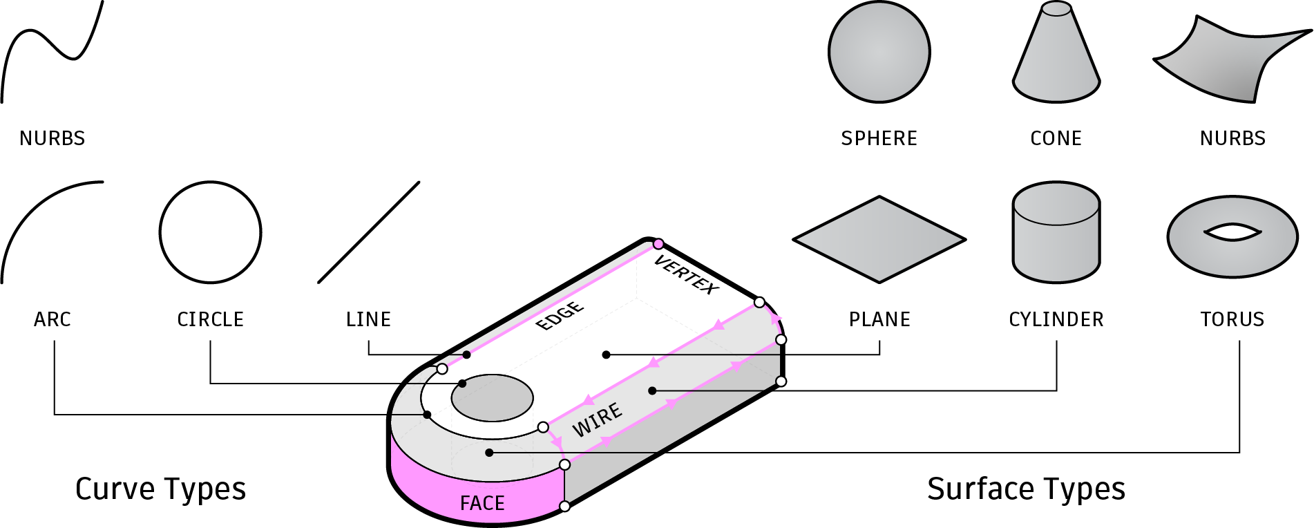
<p data-start="1568" data-end="1918">SolidGen was the first generative model to directly generate boundary representation (B-rep) CAD models. B-reps define solid geometry using a combination of topological elements, vertices, edges, wires, and faces, together with associated geometric primitives, such as<strong> </strong>lines, arcs, and circle curves, and surfaces such as planes, cylinders, and spheres.</p>
<figure class="post__image"><img loading="lazy"  src="https://karlddwillis.com/media/posts/37/SolidGen-BRepEntityTypes.png" alt="" width="1902" height="764" sizes="(max-width: 1024px) 100vw, 1024px" srcset="https://karlddwillis.com/media/posts/37/responsive/SolidGen-BRepEntityTypes-xs.png 300w ,https://karlddwillis.com/media/posts/37/responsive/SolidGen-BRepEntityTypes-sm.png 480w ,https://karlddwillis.com/media/posts/37/responsive/SolidGen-BRepEntityTypes-md.png 768w ,https://karlddwillis.com/media/posts/37/responsive/SolidGen-BRepEntityTypes-lg.png 1024w"></figure>
<p class="" data-start="1568" data-end="1918"><em>SolidGen</em> constructs B-rep geometry sequentially, predicting one topological element at a time—starting from vertices, then edges, and finally faces. Each element is built with full awareness of the ones that came before, allowing the model to maintain a coherent, watertight structure throughout the generation process.</p>
<figure class="post__image"><img loading="lazy"  src="https://karlddwillis.com/media/posts/37/SolidGen-Representation-Animate.gif" alt="" width="3000" height="707"></figure>
<p class="" data-start="1920" data-end="2352">At the heart of SolidGen is the Indexed B-rep representation. This framework encodes the hierarchical structure of a B-rep solid and explicitly tracks references between elements. As shown above, a face references a loop of edges, which in turn references vertices. This indexed structure is crucial for modeling valid B-reps and enables the model to "point back" to previously generated entities using a pointer network.</p>
<figure class="post__image"><img loading="lazy"  src="https://karlddwillis.com/media/posts/37/SolidGen-Architecture-Animate.gif" alt="" width="1810" height="864"></figure>
<p data-start="2354" data-end="2653">The SolidGen architecture (shown above) is based on Transformers and two-level pointer networks for the direct synthesis of B-reps without supervision from a sequence of CAD modeling operations. The architecture enables the generation of vertices, edges, and faces, allowing us to build the complete B-rep topology. </p>
<p><video loading="lazy" width="665" height="333" controls="controls">
<source src="https://www.karlddwillis.com/media/files/SolidGenAnimation.mp4" type="video/mp4" /></video></p>
<p data-start="2655" data-end="2979">The animation above shows the step-by-step process of B-rep generation in SolidGen:  edges are generated that reference vertices then faces are formed from loops of edges. As each element is generated, it is integrated into the growing structure, building up a complete and coherent B-rep solid. This highlights how SolidGen learns to construct geometry and topology together, enabling the direct synthesis of editable CAD models.</p>
<h3 data-start="2986" data-end="3039">BrepGen: Structured Latent Geometry with Diffusion</h3>
<p class="" data-start="3041" data-end="3097"><em>BrepGen</em> takes a diffusion-based approach that produces B-reps with higher fidelity and more flexible structure. Rather than generating geometry element-by-element in a strict sequence, as SolidGen does, BrepGen operates on a structured latent geometry representation that encodes each B-rep as a hierarchical tree (shown in the figure below). The root node represents the solid, with child nodes for faces, edges, and vertices, each encoding geometric features from sampled UV points. Shared topology is captured through node duplication, allowing the model to implicitly learn mating and adjacency relationships.</p>
<figure class="post__image"><img loading="lazy"  src="https://karlddwillis.com/media/posts/37/BrepGen-Representation.png" alt="" width="9200" height="2520" sizes="(max-width: 1024px) 100vw, 1024px" srcset="https://karlddwillis.com/media/posts/37/responsive/BrepGen-Representation-xs.png 300w ,https://karlddwillis.com/media/posts/37/responsive/BrepGen-Representation-sm.png 480w ,https://karlddwillis.com/media/posts/37/responsive/BrepGen-Representation-md.png 768w ,https://karlddwillis.com/media/posts/37/responsive/BrepGen-Representation-lg.png 1024w"></figure>
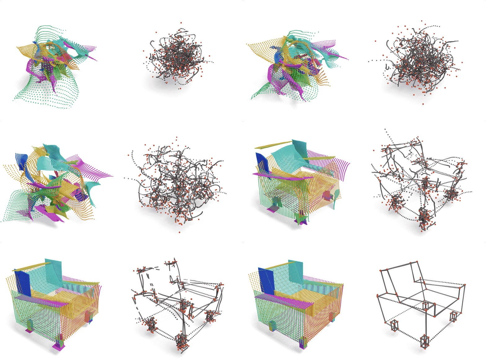
<p class="" data-start="4155" data-end="4502">Using a transformer-based denoising diffusion model, BrepGen reconstructs the solid from root to leaves, first generating global structure, then refining local geometry. After generation, duplicated nodes are merged to recover connectivity, trimming faces from closed edge loops and assembling a complete, watertight B-rep. This approach enables the generation of more intricate surfaces and topologies, including curved, doubly-connected, and freeform geometry that’s difficult to express through sequential modeling alone.</p>
<figure class="post__image"><img loading="lazy"  src="https://karlddwillis.com/media/posts/37/BrepGen-System.png" alt="" width="2556" height="1058" sizes="(max-width: 1024px) 100vw, 1024px" srcset="https://karlddwillis.com/media/posts/37/responsive/BrepGen-System-xs.png 300w ,https://karlddwillis.com/media/posts/37/responsive/BrepGen-System-sm.png 480w ,https://karlddwillis.com/media/posts/37/responsive/BrepGen-System-md.png 768w ,https://karlddwillis.com/media/posts/37/responsive/BrepGen-System-lg.png 1024w"></figure>
<p data-start="4155" data-end="4502">The animation below illustrates the denoising diffusion process in 3D. On the left, surface geometry is progressively refined from noisy samples into clean UV grid patterns representing surfaces. On the right, vertex and edge positions emerge from coarse, disordered points into structured topological elements. </p>
<p><video loading="lazy" width="665" height="333" controls="controls" data-mce-fragment="1">
<source src="https://www.karlddwillis.com/media/files/BrepGen-Diffusion-01.mp4" type="video/mp4" /></video></p>
<p data-start="4155" data-end="4502">We found that BrepGen produces geometry with improved structural complexity and visual fidelity compared to SolidGen. In the figure below, you can see that BrepGen generates more diverse and expressive shapes with fewer open boundaries and self-intersecting edges.</p>
<figure class="post__image"><img loading="lazy"  src="https://karlddwillis.com/media/posts/37/BrepGen-Unconditional.jpg" alt="" width="3000" height="1092" sizes="(max-width: 1024px) 100vw, 1024px" srcset="https://karlddwillis.com/media/posts/37/responsive/BrepGen-Unconditional-xs.jpg 300w ,https://karlddwillis.com/media/posts/37/responsive/BrepGen-Unconditional-sm.jpg 480w ,https://karlddwillis.com/media/posts/37/responsive/BrepGen-Unconditional-md.jpg 768w ,https://karlddwillis.com/media/posts/37/responsive/BrepGen-Unconditional-lg.jpg 1024w"></figure>
<p data-start="4504" data-end="4821">BrepGen performs well across a range of tasks, from generating novel shapes to completing partial geometry such as in the figure below. The grey geometry on the left is the input to the model, and the blue geometry shows completions on each row.</p>
<figure class="post__image"><img loading="lazy"  src="https://karlddwillis.com/media/posts/37/BrepGen-Inpaint.png" alt="" width="2000" height="1160" sizes="(max-width: 1024px) 100vw, 1024px" srcset="https://karlddwillis.com/media/posts/37/responsive/BrepGen-Inpaint-xs.png 300w ,https://karlddwillis.com/media/posts/37/responsive/BrepGen-Inpaint-sm.png 480w ,https://karlddwillis.com/media/posts/37/responsive/BrepGen-Inpaint-md.png 768w ,https://karlddwillis.com/media/posts/37/responsive/BrepGen-Inpaint-lg.png 1024w"></figure>
<p class="" data-start="4504" data-end="4821">BrepGen significantly improves over prior models in both geometric diversity and B-rep validity, generating more expressive and topologically varied solids. Because it operates directly within structured B-rep space, its outputs are immediately compatible with modern CAD pipelines, an enabler for real-world design, editing, and downstream applications.</p>
<h3 data-start="112" data-end="152">Toward General-Purpose CAD Generation</h3>
<p class="" data-start="154" data-end="583">SolidGen and BrepGen represent a step toward more capable and flexible generative models for CAD, models that move beyond legacy parametric modeling sequences to generate geometry directly in the native B-rep format. This shift makes it possible to support a wider range of design workflows, including direct modeling and freeform geometry, while producing outputs that are immediately usable in real-world CAD systems. By learning to generate both geometry and topology together, these models open new directions for intelligent design tools that can suggest, complete, and synthesize complex 3D forms. As generative modeling continues to advance, we see direct B-rep generation as a foundational capability for the next generation of ML-assisted CAD tools.</p>
<p><strong>SolidGen Paper:</strong> <a href="https://arxiv.org/abs/2203.13944">SolidGen: An Autoregressive Model for Direct B-rep Synthesis</a> (TMLR 2022)</p>
<p><strong>BrepGen Paper:</strong> <a href="https://arxiv.org/abs/2401.15563">BrepGen: A B-Rep Generative Diffusion Model with Structured Latent Geometry</a> (SIGGRAPH 2024)</p>
<p><strong>BrepGen Code:</strong> <a href="https://github.com/samxuxiang/BrepGen">https://github.com/samxuxiang/BrepGen</a> </p>
<p><strong>Created By:</strong> Autodesk Research / SFU</p>
<p><strong>Co-Authors:</strong> Pradeep Kumar Jayaraman (SolidGen lead author), Xiang Xu (BrepGen lead author), Joe Lambourne, Zhengqing Wang, Nishkrit Desai, Aditya Sanghi, Nigel Morris, Yasutaka Furukawa</p>
<p> </p>
            ]]>
        </content>
    </entry>
    <entry>
        <title>Sequence-based CAD Generative Models</title>
        <author>
            <name>Karl D.D. Willis</name>
        </author>
        <link href="https://karlddwillis.com/sequence-based-cad-generative-models/"/>
        <id>https://karlddwillis.com/sequence-based-cad-generative-models/</id>
        <media:content url="https://karlddwillis.com/media/posts/36/SkexGen_00_Featured.png" medium="image" />
            <category term="Research"/>

        <updated>2022-07-26T20:08:49-07:00</updated>
            <summary type="html">
                <![CDATA[
                        <img src="https://karlddwillis.com/media/posts/36/SkexGen_00_Featured.png" alt="" />
                    How can machine learning represent and generate 2D sketches and 3D mechanical&hellip;
                ]]>
            </summary>
        <content type="html">
            <![CDATA[
                    <p><img src="https://karlddwillis.com/media/posts/36/SkexGen_00_Featured.png" class="type:primaryImage" alt="" /></p>
                <p class="" data-start="480" data-end="697">How can machine learning represent and generate 2D sketches and 3D mechanical parts in ways that are structured, controllable, and useful for design workflows? Together with collaborators from Simon Fraser University, we developed a pair of generative models for CAD aimed at learning how humans design:</p>
<ul data-start="785" data-end="1120">
<li class="" data-start="785" data-end="915">
<p class="" data-start="787" data-end="915"><strong data-start="787" data-end="798"><a href="https://arxiv.org/abs/2207.04632">SkexGen</a></strong>, a model that disentangles topology and geometry into separate codebooks for generating sketches and extruded parts.</p>
</li>
<li class="" data-start="916" data-end="1120">
<p class="" data-start="918" data-end="1120"><strong data-start="918" data-end="954"><a href="https://arxiv.org/abs/2307.00149">Hierarchical Neural Coding</a> (HNC)</strong>, an extension of this work that introduces a multi-level codebook structure, enabling even more flexible and hierarchical control over generation and completion.</p>
</li>
</ul>
<p class="" data-start="1122" data-end="1308">These models open up new possibilities for AI-assisted CAD, allowing for partial edits, hybrid designs, and interactive generation grounded in the patterns of real-world design data.</p>
<h3 data-start="1315" data-end="1344">Learning From Human Design Sequences </h3>
<p class="" data-start="1346" data-end="1628">Parametric CAD modeling relies on sketch and extrude operations to define 3D shapes. These sketches are typically defined with constraints and dimensions that support quick edits and design variations. However, setting up constraints is time-consuming and requires expert knowledge.</p>
<p data-start="1346" data-end="1628"><video loading="lazy" width="665" height="auto" controls="controls">
		<source src="https://www.karlddwillis.com/media/files/SkexGen_02_SketchConstraintsCut.mp4" type="video/mp4" />
	</video></p>
<p class="" data-start="1630" data-end="1980">Take the example of a heat sink design. Parametric constraints can be used to drive the number of fins, spacing between fins, and the overall body shape. This allows the design to be updated quickly and consistently across the model.</p>
<figure class="post__image post__image--center"><img loading="lazy"  src="https://karlddwillis.com/media/posts/36/SkexGen_03_HeatSink.png" alt="Example of design variation using parametric CAD" width="2580" height="1430" sizes="(max-width: 1024px) 100vw, 1024px" srcset="https://karlddwillis.com/media/posts/36/responsive/SkexGen_03_HeatSink-xs.png 300w ,https://karlddwillis.com/media/posts/36/responsive/SkexGen_03_HeatSink-sm.png 480w ,https://karlddwillis.com/media/posts/36/responsive/SkexGen_03_HeatSink-md.png 768w ,https://karlddwillis.com/media/posts/36/responsive/SkexGen_03_HeatSink-lg.png 1024w"></figure>
<p data-start="1982" data-end="2029">However, defining such constraints is a manual process and requires a deep understanding of the underlying geometry. Here are the parameters driving the heatsink design, it's a job for an expert.</p>
<div> </div>
<div><figure class="post__image post__image--center"><img loading="lazy"  src="https://karlddwillis.com/media/posts/36/SkexGen_04_HeatSinkParams.png" alt="Parameters needed to model design variation for a heat sink." width="2628" height="1398" sizes="(max-width: 1024px) 100vw, 1024px" srcset="https://karlddwillis.com/media/posts/36/responsive/SkexGen_04_HeatSinkParams-xs.png 300w ,https://karlddwillis.com/media/posts/36/responsive/SkexGen_04_HeatSinkParams-sm.png 480w ,https://karlddwillis.com/media/posts/36/responsive/SkexGen_04_HeatSinkParams-md.png 768w ,https://karlddwillis.com/media/posts/36/responsive/SkexGen_04_HeatSinkParams-lg.png 1024w"></figure></div>
<p class="" data-start="2031" data-end="2300">What if we could learn from how people design and use that to generate new, editable designs automatically? What if we could capture the patterns and structure embedded in real-world sketches and parts and use that as the basis for fast, controllable design generation?</p>
<h3>SkexGen (SKetch and EXtrude GENerative model)</h3>
<p>SkexGen tackles this problem by firstly separating out the topology from geometry in our representation, so they can be controlled individually downstream.</p>
<figure class="post__image post__image--center"><img loading="lazy"  src="https://karlddwillis.com/media/posts/36/SkexGen_05_TopoGeo.gif" alt="SkexGen sketch representation of topology and geometry." width="2000" height="819"></figure>
<p>As with prior work we generate a sequence of tokens based on the hierarchy of curves, loops, faces, and extrusions found in sketch and extrude construction sequences.</p>
<figure class="post__image post__image--center"><img loading="lazy"  src="https://karlddwillis.com/media/posts/36/SkexGen_06_Representation.gif" alt="SkexGen sketch and extrude representation." width="1440" height="720"></figure>
<p>Here is where it gets interesting, these tokens are fed into separate Transformer encoders to encode the topology, geometry, and extrude information into separate quantized codebooks. A separate sketch and extrude decoder is used to generate a CAD construction sequence.</p>
<figure class="post__image post__image--center"><img loading="lazy"  src="https://karlddwillis.com/media/posts/36/SkexGen_07_Architecture.gif" alt="SkexGen architecture." width="1440" height="720"></figure>Using this approach the sketch generation quality is excellent. The model implicitly learns symmetries and regularities in each design without ever seeing sketch constraints.</p>
<figure class="post__image post__image--center"><img loading="lazy"  src="https://karlddwillis.com/media/posts/36/SkexGen_07a_Sketches.gif" alt="Sketches generated using SkexGen." width="1200" height="1200"></figure>
<p>The same process can be used to generate 3D parts. At inference time, we can sample from the codebooks and decode them into sketches or parts. </p>
<figure class="post__image post__image--center"><img loading="lazy"  src="https://karlddwillis.com/media/posts/36/SkexGen_01_SkexGen.png" alt="SkexGen: Autoregressive Generation of CAD  Construction Sequences with Disentangled Codebooks" width="2282" height="1126" sizes="(max-width: 1024px) 100vw, 1024px" srcset="https://karlddwillis.com/media/posts/36/responsive/SkexGen_01_SkexGen-xs.png 300w ,https://karlddwillis.com/media/posts/36/responsive/SkexGen_01_SkexGen-sm.png 480w ,https://karlddwillis.com/media/posts/36/responsive/SkexGen_01_SkexGen-md.png 768w ,https://karlddwillis.com/media/posts/36/responsive/SkexGen_01_SkexGen-lg.png 1024w"></figure>
<p>The disentangled structure allows us to generate and manipulate designs in meaningful ways. When we generate 2D sketches or 3D parts we can use the same code in any of the codebooks to produce results that are similar in either topology, geometry, or extrusion parameters. Here we keep the topology code the same so the designs have similar overall structure.</p>
<figure class="post__image post__image--center"><img loading="lazy"  src="https://karlddwillis.com/media/posts/36/SkexGen_08_TopoSame.gif" alt="SkexGen generation results using the same topology code." width="1800" height="720"></figure>An entirely new capability is to mix the codes from different designs. Here we take the topology code from a design with a series of cylinders and mix it with the geometry and extrude codes from a block to get a hybrid design.</p>
<figure class="post__image post__image--center"><img loading="lazy"  src="https://karlddwillis.com/media/posts/36/SkexGen_09_CodeMix.gif" alt="Mixing topology, geometry, and extrude codes to create a hybrid design using SkexGen." width="1440" height="720"></figure>
<p><span class="css-901oao css-16my406 r-poiln3 r-bcqeeo r-qvutc0">Code mixing can also turn 😀</span><span class="css-901oao css-16my406 r-poiln3 r-bcqeeo r-qvutc0"> into 😐</span><span class="css-901oao css-16my406 r-poiln3 r-bcqeeo r-qvutc0">.</span></p>
<figure class="post__image post__image--center"><img loading="lazy"  src="https://karlddwillis.com/media/posts/36/SkexGen_10_CodeMixFace.gif" alt="Mixing topology, geometry, and extrude codes to create a hybrid design using SkexGen." width="1600" height="720"></figure>
<p> </p>
<h3 data-start="4221" data-end="4292">Hierarchical Neural Coding for Controllable CAD Model Generation</h3>
<p class="" data-start="4294" data-end="4492">While SkexGen separates design elements into discrete codebooks, our follow-up work, Hierarchical Neural Coding (HNC), takes this further by introducing structure tied to the hierachy of a CAD model.</p>
<figure class="post__image"><img loading="lazy"  style="color: var(--text-primary-color); font-family: var(--editor-font-family); font-size: inherit; font-weight: var(--font-weight-normal);" src="https://karlddwillis.com/media/posts/36/HNC-Representation.png" alt="Hierarchical tree representation of a CAD model" width="2626" height="1077" sizes="(max-width: 1024px) 100vw, 1024px" srcset="https://karlddwillis.com/media/posts/36/responsive/HNC-Representation-xs.png 300w ,https://karlddwillis.com/media/posts/36/responsive/HNC-Representation-sm.png 480w ,https://karlddwillis.com/media/posts/36/responsive/HNC-Representation-md.png 768w ,https://karlddwillis.com/media/posts/36/responsive/HNC-Representation-lg.png 1024w"></figure>
<p data-start="4294" data-end="4492">As shown above, a sketch and extrude CAD model is naturally hierarchical, consisting of several nested entities: <em>loops</em><strong data-start="273" data-end="282"> </strong>define individual 2D contours, <em>profiles</em> represent closed regions composed of one outer loop and potentially multiple inner loops, <em>solids</em> correspond to extruded profiles, and the complete <em>model</em> is composed of one or more solids. Our goal is to enable both local and global control in the generation process, where users can edit any of these entities, whether a loop, profile, solid, or the full model, and have the rest of the design update automatically in a coherent way.</p>
<figure class="post__image"><img loading="lazy"  src="https://karlddwillis.com/media/posts/36/HNC-ProblemMotivation.png" alt="" width="3464" height="1685" sizes="(max-width: 1024px) 100vw, 1024px" srcset="https://karlddwillis.com/media/posts/36/responsive/HNC-ProblemMotivation-xs.png 300w ,https://karlddwillis.com/media/posts/36/responsive/HNC-ProblemMotivation-sm.png 480w ,https://karlddwillis.com/media/posts/36/responsive/HNC-ProblemMotivation-md.png 768w ,https://karlddwillis.com/media/posts/36/responsive/HNC-ProblemMotivation-lg.png 1024w"></figure>
<p>Unfortunately this is not the case today, parametric CAD requires specialized skills and can easily fail when constraints are missing or incomplete. For example, simple edits to the table design above, such as changing leg length or tabletop size, can break the original intent, resulting in misaligned or distorted geometry. These issues highlight the limitations of current tools and the need for ML models that can better preserve design intent.</p>
<figure class="post__image"><img loading="lazy"  src="https://karlddwillis.com/media/posts/36/HNC-Generation.jpg" alt="" width="2634" height="1655" sizes="(max-width: 1024px) 100vw, 1024px" srcset="https://karlddwillis.com/media/posts/36/responsive/HNC-Generation-xs.jpg 300w ,https://karlddwillis.com/media/posts/36/responsive/HNC-Generation-sm.jpg 480w ,https://karlddwillis.com/media/posts/36/responsive/HNC-Generation-md.jpg 768w ,https://karlddwillis.com/media/posts/36/responsive/HNC-Generation-lg.jpg 1024w"></figure>
<p class="" data-start="116" data-end="425">Our HNC generative model captures CAD design intent as a three-level tree of neural codes, spanning local geometry to global part structure. This representation enables generation and completion of CAD models based on partial inputs, directly specified code trees, or unconditional generation (shown above). The model learns these hierarchical codebooks using a novel VQ-VAE with masked skip connections, producing clean, interpretable representations learned from a large dataset of sketch-and-extrude models. A two-stage transformer then maps between geometry and code trees, allowing flexible, controllable generation. The final designs are outputed as modeling operations and converted into a standard B-Rep format for use in CAD tools.</p>
<figure class="post__image"><img loading="lazy"  src="https://karlddwillis.com/media/posts/36/HNC-Applications-UserEdit.jpg" alt="" width="2783" height="995" sizes="(max-width: 1024px) 100vw, 1024px" srcset="https://karlddwillis.com/media/posts/36/responsive/HNC-Applications-UserEdit-xs.jpg 300w ,https://karlddwillis.com/media/posts/36/responsive/HNC-Applications-UserEdit-sm.jpg 480w ,https://karlddwillis.com/media/posts/36/responsive/HNC-Applications-UserEdit-md.jpg 768w ,https://karlddwillis.com/media/posts/36/responsive/HNC-Applications-UserEdit-lg.jpg 1024w"></figure>
<p data-start="116" data-end="425">The figure above illustrates how user edits can be automatically propagated across the design to maintain consistent structure and preserve design intent. Whether modifying the spacing of facial features in a sketch (left) or adjusting the dimensions of a table design (right), the model updates the rest of the geometry in a coherent way. </p>
<figure class="post__image"><img loading="lazy"  src="https://karlddwillis.com/media/posts/36/HNC-Applications-Autocomplete.jpg" alt="" width="2506" height="995" sizes="(max-width: 1024px) 100vw, 1024px" srcset="https://karlddwillis.com/media/posts/36/responsive/HNC-Applications-Autocomplete-xs.jpg 300w ,https://karlddwillis.com/media/posts/36/responsive/HNC-Applications-Autocomplete-sm.jpg 480w ,https://karlddwillis.com/media/posts/36/responsive/HNC-Applications-Autocomplete-md.jpg 768w ,https://karlddwillis.com/media/posts/36/responsive/HNC-Applications-Autocomplete-lg.jpg 1024w"></figure>
<p>The figure above demonstrates the model’s ability to autocomplete partial geometry into complete, realistic designs. Given an incomplete sketch (left) or part (right), the model generates multiple coherent completions, each reflecting plausible design intent. </p>
<h3 data-start="5406" data-end="5419">Reimagining Design Tools</h3>
<p class="" data-start="5421" data-end="5832">Together, SkexGen and HNC reflect our ongoing effort to learn expressive and controllable representations for CAD design. With SkexGen, we introduced a disentangled codebook model that separates topology, geometry, and extrusion. With HNC, we take this further, learning hierarchical code structures that reflect how designs are composed and allowing more granular control over the generative process. Our aim is to build tools that support the creative intent of designers. Tools that don’t replace human input, but <em>amplify it</em><strong data-start="5948" data-end="5962"> </strong>by making the design space more navigable, editable, and interactive. </p>
<p><strong>SkexGen Paper:</strong> <a href="https://arxiv.org/abs/2207.04632" rel="nofollow">SkexGen: Autoregressive Generation of CAD Construction Sequences with Disentangled Codebooks</a> (ICML 2022)</p>
<p><strong>SkexGen Code:</strong> <a href="https://github.com/samxuxiang/SkexGen">https://github.com/samxuxiang/SkexGen</a></p>
<p><strong>HNC Paper:</strong> <a href="https://arxiv.org/abs/2307.00149">Hierarchical Neural Coding for Controllable CAD Model Generation</a></p>
<p><strong>HNC Code:</strong> <a href="https://github.com/samxuxiang/hnc-cad">https://github.com/samxuxiang/hnc-cad</a> </p>
<p><strong>Created By:</strong> SFU / Autodesk Research</p>
<p><strong>Co-Authors:</strong> Xiang Xu (Lead author), Joe Lambourne, Chin-Yi Cheng, Pradeep Kumar Jayaraman, Yasutaka Furukawa</p>
<p> </p>
<p> </p>
            ]]>
        </content>
    </entry>
    <entry>
        <title>JoinABLe</title>
        <author>
            <name>Karl D.D. Willis</name>
        </author>
        <link href="https://karlddwillis.com/joinable/"/>
        <id>https://karlddwillis.com/joinable/</id>
        <media:content url="https://karlddwillis.com/media/posts/35/JoinABLe_Teaser.gif" medium="image" />
            <category term="Research"/>

        <updated>2022-06-21T07:35:00-07:00</updated>
            <summary type="html">
                <![CDATA[
                        <img src="https://karlddwillis.com/media/posts/35/JoinABLe_Teaser.gif" alt="" />
                    Ever wondered how physical objects with hundreds of parts get assembled in&hellip;
                ]]>
            </summary>
        <content type="html">
            <![CDATA[
                    <p><img src="https://karlddwillis.com/media/posts/35/JoinABLe_Teaser.gif" class="type:primaryImage" alt="" /></p>
                <p>Ever wondered how physical objects with hundreds of parts get assembled in CAD? It’s a tedious process that we automate by learning how pair of parts connect to form joints.</p>
<figure class="post__image post__image--center"><img loading="lazy"  src="https://karlddwillis.com/media/posts/35/JoinABLe_01_ComplexAssembly.gif" alt="A complex CAD assembly." width="600" height="600"></figure>
<p>So what does joint setup look like in CAD today? Designers manually pick edges or faces on each part and a joint is formed that constrains the two parts to one another. Once constrained the parts move as one.</p>
<p class="post__image post__image--center"><video loading="lazy" width="600" height="auto" controls="controls">
		<source src="https://www.karlddwillis.com/media/files/JoinABLe_02_Clicks.mp4" type="video/mp4" />
	</video></p>
<p>However, doing it over and over again is time consuming and error prone...</p>
<p class="post__image post__image--center"><video loading="lazy" width="600" height="auto" controls="controls">
		<source src="https://www.karlddwillis.com/media/files/JoinABLe_03_PumpAssembly.mp4" type="video/mp4" />
	</video></p>
<p>What if we could automatically create a joint to assemble a pair of parts just by looking at their shape? Could we do this without any object category labels or human guidance? Here’s how we tackle it...</p>
<figure class="post__image post__image--center"><img loading="lazy"  src="https://karlddwillis.com/media/posts/35/JoinABLe_04_PartInputOutput.jpg" alt="JoinABLe automatically creates joints to assemble a pair of parts." width="1260" height="1080" sizes="(max-width: 1024px) 100vw, 1024px" srcset="https://karlddwillis.com/media/posts/35/responsive/JoinABLe_04_PartInputOutput-xs.jpg 300w ,https://karlddwillis.com/media/posts/35/responsive/JoinABLe_04_PartInputOutput-sm.jpg 480w ,https://karlddwillis.com/media/posts/35/responsive/JoinABLe_04_PartInputOutput-md.jpg 768w ,https://karlddwillis.com/media/posts/35/responsive/JoinABLe_04_PartInputOutput-lg.jpg 1024w"></figure>
<p>We take a bottom up approach to learn how parts connect locally. We frame the problem as a categorical one and make direct predictions on a solid model's discrete set of faces/edges. We represent each part as a graph and predict a single joint connection between the two parts.</p>
<figure class="post__image post__image--center"><img loading="lazy"  src="https://karlddwillis.com/media/posts/35/JoinABLe_05_joinable_representation.gif" alt="JoinABLe represents solid models as a graph to predict a joint axis." width="2796" height="1080"></figure>
<p>The predicted faces/edges give us a joint axis to align the two parts and the final pose can be recovered using a neurally guided search.</p>
<figure class="post__image post__image--center"><img loading="lazy"  src="https://karlddwillis.com/media/posts/35/JoinABLe_06_joinable_architecture.gif" alt="JoinABLe Architecture." width="2929" height="720"></figure>
<p>JoinABLe outperforms all of the other methods we compared against and is within 0.5% of human performance on the joint axis prediction task. The image below shows how JoinABLe assembles pairs of parts in a more realistic way than a point cloud baseline.</p>
<figure class="post__image post__image--center"><img loading="lazy"  src="https://karlddwillis.com/media/posts/35/JoinABLe_07_Results-QualPose.jpg" alt="JoinABLe joint pose prediction comparison" width="4334" height="1080" sizes="(max-width: 1024px) 100vw, 1024px" srcset="https://karlddwillis.com/media/posts/35/responsive/JoinABLe_07_Results-QualPose-xs.jpg 300w ,https://karlddwillis.com/media/posts/35/responsive/JoinABLe_07_Results-QualPose-sm.jpg 480w ,https://karlddwillis.com/media/posts/35/responsive/JoinABLe_07_Results-QualPose-md.jpg 768w ,https://karlddwillis.com/media/posts/35/responsive/JoinABLe_07_Results-QualPose-lg.jpg 1024w"></figure>
<p>We release our code along with a new dataset of multi-part CAD assemblies containing rich information on joints, contact surfaces, holes, and the underlying assembly graph structure.</p>
<figure class="post__image post__image--center"><img loading="lazy"  src="https://karlddwillis.com/media/posts/35/JoinABLe_08_AssemblyMosaic.jpg" alt="Fusion 360 Gallery Assembly Dataset." width="2550" height="3300" sizes="(max-width: 1024px) 100vw, 1024px" srcset="https://karlddwillis.com/media/posts/35/responsive/JoinABLe_08_AssemblyMosaic-xs.jpg 300w ,https://karlddwillis.com/media/posts/35/responsive/JoinABLe_08_AssemblyMosaic-sm.jpg 480w ,https://karlddwillis.com/media/posts/35/responsive/JoinABLe_08_AssemblyMosaic-md.jpg 768w ,https://karlddwillis.com/media/posts/35/responsive/JoinABLe_08_AssemblyMosaic-lg.jpg 1024w"></figure>
<p><strong>Paper:</strong> <a href="https://arxiv.org/abs/2111.12772" rel="nofollow">JoinABLe: Learning Bottom-up Assembly of Parametric CAD Joints</a> (CVPR 2022)<br><strong>Code:</strong> <a href="https://github.com/AutodeskAILab/JoinABLe">https://github.com/AutodeskAILab/JoinABLe</a> <br><strong>Dataset:</strong> <a href="https://github.com/AutodeskAILab/Fusion360GalleryDataset">https://github.com/AutodeskAILab/Fusion360GalleryDataset</a> </p>
<p><strong>Created By:</strong> Autodesk Research / MIT</p>
<p><strong>Co-Authors:</strong> Pradeep Kumar Jayaraman, Hang Chu, Yunsheng Tian, Yifei Li, Daniele Grandi, Aditya Sanghi, Linh Tran, Joe Lambourne, Wojciech Matusik, Armando Solar-Lezama.</p>
            ]]>
        </content>
    </entry>
    <entry>
        <title>Deep Learning with Solid Models</title>
        <author>
            <name>Karl D.D. Willis</name>
        </author>
        <link href="https://karlddwillis.com/deep-learning-with-solid-models/"/>
        <id>https://karlddwillis.com/deep-learning-with-solid-models/</id>
        <media:content url="https://karlddwillis.com/media/posts/34/01-teaser.gif" medium="image" />
            <category term="Research"/>

        <updated>2021-06-27T15:25:05-07:00</updated>
            <summary type="html">
                <![CDATA[
                        <img src="https://karlddwillis.com/media/posts/34/01-teaser.gif" alt="Deep Learning with Solid Models" />
                    The objects around us, chairs, cars, devices etc., are almost always designed&hellip;
                ]]>
            </summary>
        <content type="html">
            <![CDATA[
                    <p><img src="https://karlddwillis.com/media/posts/34/01-teaser.gif" class="type:primaryImage" alt="Deep Learning with Solid Models" /></p>
                <p>The objects around us, chairs, cars, devices etc., are almost always designed as solid models in CAD, but surprisingly few deep learning approaches have been used to date. Making it difficult to explore how learning based methods might enhance future CAD tools with features such as auto-complete or interpolation between CAD models. Part of the challenge has been the availability of suitable data, and part teaching these algorithms to speak CAD. We tackled both of these challenges over the course of several collaborations between Autodesk Research and MIT, Brown Universty, and UCL, with results published at CVPR and SIGGRAPH.</p>
<p>Solid models use the boundary representation, or B-Rep. Think of a B-Rep as a watertight mesh where the faces don’t need to be flat and can be trimmed to any shape. These faces are ‘glued’ together, with the topology forming a well structured graph.</p>
<figure class="post__image"><img loading="lazy"  src="https://karlddwillis.com/media/posts/34/02-brep.png" alt="Boundary representation (B-Rep) solid model diagram" width="1600" height="1245" sizes="(max-width: 1024px) 100vw, 1024px" srcset="https://karlddwillis.com/media/posts/34/responsive/02-brep-xs.png 300w ,https://karlddwillis.com/media/posts/34/responsive/02-brep-sm.png 480w ,https://karlddwillis.com/media/posts/34/responsive/02-brep-md.png 768w ,https://karlddwillis.com/media/posts/34/responsive/02-brep-lg.png 1024w"></figure>
<p>In <em>UV-Net</em> (<a href="https://arxiv.org/abs/2006.10211" target="_blank" rel="nofollow noopener">Paper</a>, <a href="https://github.com/AutodeskAILab/UV-Net" target="_blank" rel="nofollow noopener">Code</a>) we use this graph with a GNN and sample a point grid on each face for use with a CNN. This combination outperforms mesh and point cloud methods on both classification and segmentation.</p>
<figure class="post__image"><img loading="lazy"  src="https://karlddwillis.com/media/posts/34/03-uvnet.gif" alt="UV-Net" width="1920" height="850"></figure>
<p>In <em>BRepNet</em> (<a href="https://arxiv.org/abs/2104.00706" target="_blank" rel="nofollow noopener">Paper</a>, <a href="https://github.com/AutodeskAILab/BRepNet" target="_blank" rel="nofollow noopener">Code</a>) we show that convolutional kernels can be applied with respect to oriented coedges to outperform both network and heuristic methods on segmentation.</p>
<figure class="post__image"><img loading="lazy"  src="https://karlddwillis.com/media/posts/34/04-brepnet.gif" alt="" width="1920" height="919"></figure>
<p>Along with <em>BRepNet</em> we also release a new <a href="https://github.com/AutodeskAILab/Fusion360GalleryDataset/blob/master/docs/segmentation.md" target="_blank" rel="nofollow noopener">segmentation dataset</a> with over 35k CAD models in B-Rep, mesh, and point cloud representations.</p>
<figure class="post__image"><img loading="lazy"  src="https://karlddwillis.com/media/posts/34/05-segmentation_mosaic.gif" alt="Fusion 360 Gallery segmentation dataset" width="1920" height="1080"></figure>
<p>So if you have access to solid model data, it can really help with classification and segmentation. But what about other tasks? One long sought after goal in CAD is to reverse engineer a CAD model when the modeling history is not available. We tackle this problem with a new representation, the <em>Zone Graph </em>(<a href="https://arxiv.org/abs/2104.03900" target="_blank" rel="nofollow noopener">Paper</a>, <a href="https://github.com/brownvc/zone-graphs" target="_blank" rel="nofollow noopener">Code</a>), where each zone is a solid region formed by extending all B-Rep faces and partitioning space with them. </p>
<figure class="post__image"><img loading="lazy"  src="https://karlddwillis.com/media/posts/34/06-zone_graphs.gif" alt="Zone Graphs" width="800" height="1000"></figure>For <em>Zone Graphs</em> we train on the <em>Fusion 360 Gallery</em> reconstruction dataset (<a href="https://arxiv.org/abs/2010.02392" target="_blank" rel="nofollow noopener">Paper</a>, <a href="https://github.com/AutodeskAILab/Fusion360GalleryDataset" target="_blank" rel="nofollow noopener">Code</a>) containing human designed CAD modeling sequences. </p>
<figure class="post__image"><img loading="lazy"  src="https://karlddwillis.com/media/posts/34/07-reconstruction_seq.gif" alt="Fusion 360 Gallery reconstruction dataset" width="1600" height="900"></figure>
<p>Finally, in a CVPR workshop paper we explore how we might synthesize solid models by first generating plausible engineering sketches using transformers (<a href="https://arxiv.org/abs/2104.09621" target="_blank" rel="nofollow noopener">Paper</a>).</p>
<figure class="post__image"><img loading="lazy"  src="https://karlddwillis.com/media/posts/34/08-sketch.gif" alt="Engineering Sketch Generation for Computer Aided Design" width="1600" height="1600"></figure>
<p><strong>Created By:</strong> Autodesk Research / MIT / Brown University / UCL</p>
<p><strong>Co-Authors:</strong> Pradeep Kumar Jayaraman, Joe Lambourne, Xianghao Xu, Wenzhe Peng, Aditya Sanghi, Yewen Pu, Hang Chu, Tao Du, Wojciech Matusik, Hooman Shayani, Armando Solar-Lezama, Daniel Ritchie, Thomas Davies, Nigel Morris, Peter Meltzer, Jieliang (Rodger) Luo, Chin-Yi Cheng</p>
            ]]>
        </content>
    </entry>
    <entry>
        <title>Generative Design 2.5 Axis Milling Constraints</title>
        <author>
            <name>Karl D.D. Willis</name>
        </author>
        <link href="https://karlddwillis.com/generative-design-25-axis-milling-constraints/"/>
        <id>https://karlddwillis.com/generative-design-25-axis-milling-constraints/</id>
        <media:content url="https://karlddwillis.com/media/posts/32/2.5Axis-MJK-PD.jpg" medium="image" />
            <category term="Product"/>

        <updated>2019-10-05T21:44:16-07:00</updated>
            <summary type="html">
                <![CDATA[
                        <img src="https://karlddwillis.com/media/posts/32/2.5Axis-MJK-PD.jpg" alt="" />
                    Generative Design has traditionaly produced organic forms that, while lightweight, are difficult and&hellip;
                ]]>
            </summary>
        <content type="html">
            <![CDATA[
                    <p><img src="https://karlddwillis.com/media/posts/32/2.5Axis-MJK-PD.jpg" class="type:primaryImage" alt="" /></p>
                <div class="left">
<p>Generative Design has traditionaly produced organic forms that, while lightweight, are difficult and costly to manufacture. Together with a multi-disciplinary cross-org team, we developed a manufacturing constraint for generative design in Autodesk Fusion 360 to produce optimized 2.5 Axis millable designs. Not only is 2.5 Axis milling very common and fast, the designs produced break from the 'organic look' and appear much closer to conventional human design.</p>
<p>Asides from shape synthesis, another focus of the project was greater CAD edit-ability. Enabling Fusion 360 users to fine-tune a design after an optimized solution has been generated. A great example is the motorcycle triple clamp from MJK Performance, where they performed minor edits and styling to match their brand. </p>
<p>The 2.5 Axis Milling Constrant for generative design was announced during the Autodesk University manufacturing keynote and later released in Fusion 360.</p>
<p><strong>Created By:</strong> Autodesk Research / Autodesk Fusion 360 / Autodesk Forge Collaboration</p>
<p><strong>Selected Press:</strong> <a href="https://www.mmsonline.com/articles/generative-design-generates-new-interest-in-a-range-of-manufacturing-options">Modern Machine Shop</a>  </p>
</div>
<div class="right">
<p><img loading="lazy" src="https://karlddwillis.com/media/posts/32/2.5Axis-AU.jpg" alt="Autodesk University Manufacturing Keynote" sizes="(max-width: 1024px) 100vw, 1024px" srcset="https://karlddwillis.com/media/posts/32/responsive/2.5Axis-AU-xs.jpg 300w ,https://karlddwillis.com/media/posts/32/responsive/2.5Axis-AU-sm.jpg 480w ,https://karlddwillis.com/media/posts/32/responsive/2.5Axis-AU-md.jpg 768w ,https://karlddwillis.com/media/posts/32/responsive/2.5Axis-AU-lg.jpg 1024w"></p>
<p><img loading="lazy" src="https://karlddwillis.com/media/posts/32/2.5Axis-MJK-Comparison.jpg" alt="Generative Design Manufacturing Constraint Comparison" sizes="(max-width: 1024px) 100vw, 1024px" srcset="https://karlddwillis.com/media/posts/32/responsive/2.5Axis-MJK-Comparison-xs.jpg 300w ,https://karlddwillis.com/media/posts/32/responsive/2.5Axis-MJK-Comparison-sm.jpg 480w ,https://karlddwillis.com/media/posts/32/responsive/2.5Axis-MJK-Comparison-md.jpg 768w ,https://karlddwillis.com/media/posts/32/responsive/2.5Axis-MJK-Comparison-lg.jpg 1024w"></p>
<p> </p>
<p><img loading="lazy" src="https://karlddwillis.com/media/posts/32/2.5Axis-MJK-Design-BeforeAfter.gif" alt="Before and After Customer Stylization"></p>
<p> </p>
<p><img loading="lazy" src="https://karlddwillis.com/media/posts/32/2.5Axis-MJK-Part-Top.jpg" alt="MJK Triple Clamp - Top Clamp" sizes="(max-width: 1024px) 100vw, 1024px" srcset="https://karlddwillis.com/media/posts/32/responsive/2.5Axis-MJK-Part-Top-xs.jpg 300w ,https://karlddwillis.com/media/posts/32/responsive/2.5Axis-MJK-Part-Top-sm.jpg 480w ,https://karlddwillis.com/media/posts/32/responsive/2.5Axis-MJK-Part-Top-md.jpg 768w ,https://karlddwillis.com/media/posts/32/responsive/2.5Axis-MJK-Part-Top-lg.jpg 1024w"></p>
<p><img loading="lazy" src="https://karlddwillis.com/media/posts/32/2.5Axis-MJK-Part-Bottom.jpg" alt="MJK Triple Clamp - Bottom Clamp" sizes="(max-width: 1024px) 100vw, 1024px" srcset="https://karlddwillis.com/media/posts/32/responsive/2.5Axis-MJK-Part-Bottom-xs.jpg 300w ,https://karlddwillis.com/media/posts/32/responsive/2.5Axis-MJK-Part-Bottom-sm.jpg 480w ,https://karlddwillis.com/media/posts/32/responsive/2.5Axis-MJK-Part-Bottom-md.jpg 768w ,https://karlddwillis.com/media/posts/32/responsive/2.5Axis-MJK-Part-Bottom-lg.jpg 1024w"></p>
</div>
            ]]>
        </content>
    </entry>
    <entry>
        <title>GAMMA: Space Exploration Lander</title>
        <author>
            <name>Karl D.D. Willis</name>
        </author>
        <link href="https://karlddwillis.com/space-exploration-lander/"/>
        <id>https://karlddwillis.com/space-exploration-lander/</id>
        <media:content url="https://karlddwillis.com/media/posts/31/02_full-lander.jpg" medium="image" />
            <category term="Research"/>

        <updated>2019-09-09T21:26:19-07:00</updated>
            <summary type="html">
                <![CDATA[
                        <img src="https://karlddwillis.com/media/posts/31/02_full-lander.jpg" alt="" />
                    Scientists think the most likely places to find extraterrestrial life in our&hellip;
                ]]>
            </summary>
        <content type="html">
            <![CDATA[
                    <p><img src="https://karlddwillis.com/media/posts/31/02_full-lander.jpg" class="type:primaryImage" alt="" /></p>
                <div class="left">
<p>Scientists think the most likely places to find extraterrestrial life in our solar system are the moons of Saturn and Jupiter — hundreds of millions of miles away from Earth. Creating an interplanetary lander that can travel extreme distances in the harsh conditions of space presents a massive challenge. Autodesk and NASA’s Jet Propulsion Laboratory teamed up to explore new approaches to design and manufacturing processes for space exploration, applying generative-design technology.</p>
<p>I was fortunate enough to lead a multi-disciplinary team at Autodesk through the software prototyping, design, and manufacture of the concept lander. Every kilogram of mass that can be cut from the structural payload enables a critical increase in scientific instruments that can be launched. GAMMA leverages generative design and advanced manufacturing to achieve a mass reduction of 35% for the main structural component of the lander, compared to a conventional design.</p>
<p>GAMMA is the most complex generative design to date, meeting some of the most rigorous engineering standards to answer one of the grandest challenges – the discovery of life beyond earth.</p>
<p><strong>Created by:</strong> Karl Willis, Daniele Grandi, Andreas Bastian, Arthur Harsuvanakit, John Schmier, Mark Davis, Raul Polit Casillas, Rafael Martinez, Christine Gebara, Tom Cwik</p>
<p><strong>Awards: </strong><a href="https://www.fastcompany.com/90386309/innovation-by-design-2019-north-america">Best Design - North America Finalist</a> / <a href="https://www.fastcompany.com/90386252/innovation-by-design-2019-experimental">Experimental Finalist</a> / <a href="https://www.fastcompany.com/90386276/innovation-by-design-2019-mobility">Mobility Finalist</a>, Fast Company Innovation by Design Awards 2019, <a href="https://designawards.core77.com/2019/Strategy-Research">Strategy &amp; Research Award Runner Up</a> / <a href="https://designawards.core77.com/2019/Transportation">Transportation Award Notable</a>, Core77 Design Awards 2019, <a href="https://www.moderncasting.com/casting-competition">Best Prototype or Innovation</a>, American Foundry Society Casting of the Year Award 2019 (cast by TEI).</p>
<p><strong>Selected Press:</strong> <a href="https://www.fastcompany.com/90269399/this-is-the-most-complex-generative-design-ever-made">Fast Company</a>, <a href="http://www.bbc.com/future/story/20181129-the-ai-transforming-the-way-aircraft-are-built">BBC</a>, <a href="https://www.theverge.com/2018/11/13/18091448/nasa-ai-autodesk-jpl-lander-europa-enceladus-artificial-intelligence-generative-design">The Verge</a>, <a href="https://www.mmsonline.com/articles/generative-design-generates-new-interest-in-a-range-of-manufacturing-options">Modern Machine Shop</a>, <a href="https://www.space.com/42425-organically-inspired-planetary-landers-nasa-autodesk.html">Space.com</a></p>
</div>
<div class="right">
<div class="video_container"><div class="post__iframe"><iframe loading="lazy" width="300" height="150" allowfullscreen="allowfullscreen" class="video" frameborder="0" src="https://www.youtube.com/embed/25tvKtOF32g">
      </iframe></div></div>
<p><img loading="lazy" src="https://karlddwillis.com/media/posts/31/0_Heroimg_largeEuropaRGB.jpg" alt="Space Exploration Lander Concept Image" sizes="(max-width: 1024px) 100vw, 1024px" srcset="https://karlddwillis.com/media/posts/31/responsive/0_Heroimg_largeEuropaRGB-xs.jpg 300w ,https://karlddwillis.com/media/posts/31/responsive/0_Heroimg_largeEuropaRGB-sm.jpg 480w ,https://karlddwillis.com/media/posts/31/responsive/0_Heroimg_largeEuropaRGB-md.jpg 768w ,https://karlddwillis.com/media/posts/31/responsive/0_Heroimg_largeEuropaRGB-lg.jpg 1024w"></p>
<p><img loading="lazy" src="https://karlddwillis.com/media/posts/31/07_TEI.jpg" alt="Space Exploration Lander Casting" sizes="(max-width: 1024px) 100vw, 1024px" srcset="https://karlddwillis.com/media/posts/31/responsive/07_TEI-xs.jpg 300w ,https://karlddwillis.com/media/posts/31/responsive/07_TEI-sm.jpg 480w ,https://karlddwillis.com/media/posts/31/responsive/07_TEI-md.jpg 768w ,https://karlddwillis.com/media/posts/31/responsive/07_TEI-lg.jpg 1024w"></p>
<p><img loading="lazy" src="https://karlddwillis.com/media/posts/31/16_cncLeg.jpg" alt="Space Exploration Lander Machining" sizes="(max-width: 1024px) 100vw, 1024px" srcset="https://karlddwillis.com/media/posts/31/responsive/16_cncLeg-xs.jpg 300w ,https://karlddwillis.com/media/posts/31/responsive/16_cncLeg-sm.jpg 480w ,https://karlddwillis.com/media/posts/31/responsive/16_cncLeg-md.jpg 768w ,https://karlddwillis.com/media/posts/31/responsive/16_cncLeg-lg.jpg 1024w"></p>
<p><img loading="lazy" src="https://karlddwillis.com/media/posts/31/12_TEI.jpg" alt="Space Exploration Lander Inspection" sizes="(max-width: 1024px) 100vw, 1024px" srcset="https://karlddwillis.com/media/posts/31/responsive/12_TEI-xs.jpg 300w ,https://karlddwillis.com/media/posts/31/responsive/12_TEI-sm.jpg 480w ,https://karlddwillis.com/media/posts/31/responsive/12_TEI-md.jpg 768w ,https://karlddwillis.com/media/posts/31/responsive/12_TEI-lg.jpg 1024w"></p>
<p><img loading="lazy" src="https://karlddwillis.com/media/posts/31/28_Pier9_21.jpg" alt="Space Exploration Lander Assembly" sizes="(max-width: 1024px) 100vw, 1024px" srcset="https://karlddwillis.com/media/posts/31/responsive/28_Pier9_21-xs.jpg 300w ,https://karlddwillis.com/media/posts/31/responsive/28_Pier9_21-sm.jpg 480w ,https://karlddwillis.com/media/posts/31/responsive/28_Pier9_21-md.jpg 768w ,https://karlddwillis.com/media/posts/31/responsive/28_Pier9_21-lg.jpg 1024w"></p>
<p><img loading="lazy" src="https://karlddwillis.com/media/posts/31/03_Assembly.jpg" alt="Space Exploration Lander Assembly" sizes="(max-width: 1024px) 100vw, 1024px" srcset="https://karlddwillis.com/media/posts/31/responsive/03_Assembly-xs.jpg 300w ,https://karlddwillis.com/media/posts/31/responsive/03_Assembly-sm.jpg 480w ,https://karlddwillis.com/media/posts/31/responsive/03_Assembly-md.jpg 768w ,https://karlddwillis.com/media/posts/31/responsive/03_Assembly-lg.jpg 1024w"></p>
<p><img loading="lazy" src="https://karlddwillis.com/media/posts/31/05_Assembly.jpg" alt="Space Exploration Lander Assembly" sizes="(max-width: 1024px) 100vw, 1024px" srcset="https://karlddwillis.com/media/posts/31/responsive/05_Assembly-xs.jpg 300w ,https://karlddwillis.com/media/posts/31/responsive/05_Assembly-sm.jpg 480w ,https://karlddwillis.com/media/posts/31/responsive/05_Assembly-md.jpg 768w ,https://karlddwillis.com/media/posts/31/responsive/05_Assembly-lg.jpg 1024w"></p>
<p><img loading="lazy" src="https://karlddwillis.com/media/posts/31/07_lander.jpg" alt="Space Exploration Lander Interna; Structure and Payloads" sizes="(max-width: 1024px) 100vw, 1024px" srcset="https://karlddwillis.com/media/posts/31/responsive/07_lander-xs.jpg 300w ,https://karlddwillis.com/media/posts/31/responsive/07_lander-sm.jpg 480w ,https://karlddwillis.com/media/posts/31/responsive/07_lander-md.jpg 768w ,https://karlddwillis.com/media/posts/31/responsive/07_lander-lg.jpg 1024w"></p>
<p><img loading="lazy" src="https://karlddwillis.com/media/posts/31/20_AssemblyProcess.jpg" alt="Space Exploration Lander Assembly" sizes="(max-width: 1024px) 100vw, 1024px" srcset="https://karlddwillis.com/media/posts/31/responsive/20_AssemblyProcess-xs.jpg 300w ,https://karlddwillis.com/media/posts/31/responsive/20_AssemblyProcess-sm.jpg 480w ,https://karlddwillis.com/media/posts/31/responsive/20_AssemblyProcess-md.jpg 768w ,https://karlddwillis.com/media/posts/31/responsive/20_AssemblyProcess-lg.jpg 1024w"></p>
<p><img loading="lazy" src="https://karlddwillis.com/media/posts/31/25_AUdisplayed.jpg" alt="Space Exploration Lander Exhibition at AU 2018" sizes="(max-width: 1024px) 100vw, 1024px" srcset="https://karlddwillis.com/media/posts/31/responsive/25_AUdisplayed-xs.jpg 300w ,https://karlddwillis.com/media/posts/31/responsive/25_AUdisplayed-sm.jpg 480w ,https://karlddwillis.com/media/posts/31/responsive/25_AUdisplayed-md.jpg 768w ,https://karlddwillis.com/media/posts/31/responsive/25_AUdisplayed-lg.jpg 1024w"></p>
</div>
            ]]>
        </content>
    </entry>
    <entry>
        <title>Addimation Analytics</title>
        <author>
            <name>Karl D.D. Willis</name>
        </author>
        <link href="https://karlddwillis.com/addimation-analytics/"/>
        <id>https://karlddwillis.com/addimation-analytics/</id>
        <media:content url="https://karlddwillis.com/media/posts/30/TopImage-DSC06883-Crop.jpg" medium="image" />
            <category term="Product"/>

        <updated>2015-11-30T20:13:50-08:00</updated>
            <summary type="html">
                <![CDATA[
                        <img src="https://karlddwillis.com/media/posts/30/TopImage-DSC06883-Crop.jpg" alt="" />
                    Addimation Analytics is a data analytics service to improve production efficiency in&hellip;
                ]]>
            </summary>
        <content type="html">
            <![CDATA[
                    <p><img src="https://karlddwillis.com/media/posts/30/TopImage-DSC06883-Crop.jpg" class="type:primaryImage" alt="" /></p>
                <div class="left"><em>Addimation Analytics</em> is a data analytics service to improve production efficiency in additive manufacturing (AM). By capturing key AM production metrics in real-time we enable a new level of transparency and understanding of events happening on the production floor. Despite the heavy investment in additive manufacturing technologies, answering basic questions about production metrics e.g. how much material was used this month?, is still very difficult.
<p><em>Addimation Analytics</em> solves this problem with a software data aggregator that listens to and decodes network and log activity into meaningful production information. That information is then stored in the cloud and made accessible through a real-time analytics web interface. <em>Addimation Analytics</em> supports Stratasys FDM and Polyjet 3D printers. Addimation Analytics was acquired by FATHOM in November 2015.</p>
<p><strong>Created by:</strong> Karl D.D. Willis, Wesley Smith</p>
<p><strong>Special Thanks:</strong> John Kelleher, FATHOM</p>
<p><strong>Selected Press:</strong> <a href="http://studiofathom.com/blog/3d-printing-digital-manufacturing-data-analytics/">Acquisition Press Release</a>, <a href="http://www.3ders.org/articles/20151218-fathom-gains-next-level-3d-printing-insight-with-new-data-analytics-software.html">3Ders</a></p>
</div>
<div class="right">
<p><img loading="lazy" src="https://karlddwillis.com/media/posts/30/TopImage-DSC06883-Crop.jpg" alt="Addimation Analytics" sizes="(max-width: 1024px) 100vw, 1024px" srcset="https://karlddwillis.com/media/posts/30/responsive/TopImage-DSC06883-Crop-xs.jpg 300w ,https://karlddwillis.com/media/posts/30/responsive/TopImage-DSC06883-Crop-sm.jpg 480w ,https://karlddwillis.com/media/posts/30/responsive/TopImage-DSC06883-Crop-md.jpg 768w ,https://karlddwillis.com/media/posts/30/responsive/TopImage-DSC06883-Crop-lg.jpg 1024w"></p>
<p><img loading="lazy" src="https://karlddwillis.com/media/posts/30/AnalyticsSystem.png" alt="Addimation Analytics Product Overview" sizes="(max-width: 1024px) 100vw, 1024px" srcset="https://karlddwillis.com/media/posts/30/responsive/AnalyticsSystem-xs.png 300w ,https://karlddwillis.com/media/posts/30/responsive/AnalyticsSystem-sm.png 480w ,https://karlddwillis.com/media/posts/30/responsive/AnalyticsSystem-md.png 768w ,https://karlddwillis.com/media/posts/30/responsive/AnalyticsSystem-lg.png 1024w"></p>
<p><img loading="lazy" src="https://karlddwillis.com/media/posts/30/Production-Timeline.png" alt="Production Timeline" sizes="(max-width: 1024px) 100vw, 1024px" srcset="https://karlddwillis.com/media/posts/30/responsive/Production-Timeline-xs.png 300w ,https://karlddwillis.com/media/posts/30/responsive/Production-Timeline-sm.png 480w ,https://karlddwillis.com/media/posts/30/responsive/Production-Timeline-md.png 768w ,https://karlddwillis.com/media/posts/30/responsive/Production-Timeline-lg.png 1024w"></p>
<p><img loading="lazy" src="https://karlddwillis.com/media/posts/30/Printer-Status.png" alt="Printer Status" sizes="(max-width: 1024px) 100vw, 1024px" srcset="https://karlddwillis.com/media/posts/30/responsive/Printer-Status-xs.png 300w ,https://karlddwillis.com/media/posts/30/responsive/Printer-Status-sm.png 480w ,https://karlddwillis.com/media/posts/30/responsive/Printer-Status-md.png 768w ,https://karlddwillis.com/media/posts/30/responsive/Printer-Status-lg.png 1024w"></p>
<p><img loading="lazy" src="https://karlddwillis.com/media/posts/30/Material-Usage-Cost.png" alt="Material Usage: Cost" sizes="(max-width: 1024px) 100vw, 1024px" srcset="https://karlddwillis.com/media/posts/30/responsive/Material-Usage-Cost-xs.png 300w ,https://karlddwillis.com/media/posts/30/responsive/Material-Usage-Cost-sm.png 480w ,https://karlddwillis.com/media/posts/30/responsive/Material-Usage-Cost-md.png 768w ,https://karlddwillis.com/media/posts/30/responsive/Material-Usage-Cost-lg.png 1024w"></p>
<p><img loading="lazy" src="https://karlddwillis.com/media/posts/30/Material-Inventory.png" alt="Material Inventory" sizes="(max-width: 1024px) 100vw, 1024px" srcset="https://karlddwillis.com/media/posts/30/responsive/Material-Inventory-xs.png 300w ,https://karlddwillis.com/media/posts/30/responsive/Material-Inventory-sm.png 480w ,https://karlddwillis.com/media/posts/30/responsive/Material-Inventory-md.png 768w ,https://karlddwillis.com/media/posts/30/responsive/Material-Inventory-lg.png 1024w"></p>
<p><img loading="lazy" src="https://karlddwillis.com/media/posts/30/Dashboard-Trends.png" alt="Dashboard: Trends" sizes="(max-width: 1024px) 100vw, 1024px" srcset="https://karlddwillis.com/media/posts/30/responsive/Dashboard-Trends-xs.png 300w ,https://karlddwillis.com/media/posts/30/responsive/Dashboard-Trends-sm.png 480w ,https://karlddwillis.com/media/posts/30/responsive/Dashboard-Trends-md.png 768w ,https://karlddwillis.com/media/posts/30/responsive/Dashboard-Trends-lg.png 1024w"></p>
</div>
            ]]>
        </content>
    </entry>
    <entry>
        <title>Project Wire</title>
        <author>
            <name>Karl D.D. Willis</name>
        </author>
        <link href="https://karlddwillis.com/project-wire/"/>
        <id>https://karlddwillis.com/project-wire/</id>
        <media:content url="https://karlddwillis.com/media/posts/29/MainQuadcopter.png" medium="image" />
            <category term="Product"/>

        <updated>2015-01-06T02:37:57-08:00</updated>
            <summary type="html">
                <![CDATA[
                        <img src="https://karlddwillis.com/media/posts/29/MainQuadcopter.png" alt="" />
                    Project Wire is an Autodesk design tool for creating 3D printable electronic&hellip;
                ]]>
            </summary>
        <content type="html">
            <![CDATA[
                    <p><img src="https://karlddwillis.com/media/posts/29/MainQuadcopter.png" class="type:primaryImage" alt="" /></p>
                <div class="left">
<p>Project Wire is an Autodesk design tool for creating 3D printable electronic devices. Using the unique <a href="http://www.voxel8.co/">Voxel8</a> 3D electronics printer, the design and fabrication of truly freeform three-dimensional circuits is possible for the first time. Future electronic devices will be printed rather than assembled. Fabricated layer-by-layer as a single object, rather than assembled from separate parts. The starting point is enabling the design of 3D wires embedded in printed models.</p>
<p>Project Wire has the ability to place components, route 3D wires, output multi-material print data and much more. Unlike todays devices that house printed circuit boards within a separate shell, 3D printing enables electronics to be embedded entirely within the structure of the device. The fundamentals of how we fabricate electronic devices are changing. New software tools are needed to design for new hardware capabilities.</p>
<p><strong>Created by:</strong> Karl D.D. Willis, Daniel Taub, Baoxuan Xu, Ryan Schmidt, Karel Bruneel at Autodesk.</p>
<p><strong>Special Thanks:</strong> Tim Campbell, Eric Wilhelm, John Kelleher</p>
<p><strong>Selected Press:</strong> <a href="https://venturebeat.com/2015/01/05/autodesk-unveils-project-wire-software-that-may-someday-let-anyone-3d-print-electronics/">VentureBeat</a>, <a href="https://www.fastcodesign.com/3040518/the-9-best-ideas-from-ces-2015#2">Fast Company</a>, <a href="http://www.pcmag.com/article2/0,2817,2474653,00.asp">PC Mag</a>, <a href="http://mashable.com/2015/01/15/3d-printing-circuitry/">Mashable</a>, <a href="http://gizmodo.com/this-9k-machine-could-usher-in-the-era-of-3d-printed-e-1677580682">Gizmodo</a></p>
</div>
<div class="right"><!--
<div class="video_container"><div class="post__iframe"><iframe loading="lazy" width="300" height="150" allowfullscreen="allowfullscreen" class="video" frameborder="0" src="https://www.youtube.com/embed/zbm2SSql8V8"></iframe></div></div>
!-->
<p><img loading="lazy" src="https://karlddwillis.com/media/posts/29/WireQuadcopterDraw.png" alt="Project Wire Quadcopter Draw Mode" sizes="(max-width: 1024px) 100vw, 1024px" srcset="https://karlddwillis.com/media/posts/29/responsive/WireQuadcopterDraw-xs.png 300w ,https://karlddwillis.com/media/posts/29/responsive/WireQuadcopterDraw-sm.png 480w ,https://karlddwillis.com/media/posts/29/responsive/WireQuadcopterDraw-md.png 768w ,https://karlddwillis.com/media/posts/29/responsive/WireQuadcopterDraw-lg.png 1024w"></p>
<p><img loading="lazy" src="https://karlddwillis.com/media/posts/29/quadcopterctscan730_0.jpg" alt="Quadcopter CT Scan" sizes="(max-width: 1024px) 100vw, 1024px" srcset="https://karlddwillis.com/media/posts/29/responsive/quadcopterctscan730_0-xs.jpg 300w ,https://karlddwillis.com/media/posts/29/responsive/quadcopterctscan730_0-sm.jpg 480w ,https://karlddwillis.com/media/posts/29/responsive/quadcopterctscan730_0-md.jpg 768w ,https://karlddwillis.com/media/posts/29/responsive/quadcopterctscan730_0-lg.jpg 1024w"></p>
<p><img loading="lazy" src="https://karlddwillis.com/media/posts/29/USBLEDIllustration.png" alt="USB LED Illustration" sizes="(max-width: 1024px) 100vw, 1024px" srcset="https://karlddwillis.com/media/posts/29/responsive/USBLEDIllustration-xs.png 300w ,https://karlddwillis.com/media/posts/29/responsive/USBLEDIllustration-sm.png 480w ,https://karlddwillis.com/media/posts/29/responsive/USBLEDIllustration-md.png 768w ,https://karlddwillis.com/media/posts/29/responsive/USBLEDIllustration-lg.png 1024w"></p>
<p><img loading="lazy" src="https://karlddwillis.com/media/posts/29/USBLEDPhoto.jpg" alt="USB LED Photo" sizes="(max-width: 1024px) 100vw, 1024px" srcset="https://karlddwillis.com/media/posts/29/responsive/USBLEDPhoto-xs.jpg 300w ,https://karlddwillis.com/media/posts/29/responsive/USBLEDPhoto-sm.jpg 480w ,https://karlddwillis.com/media/posts/29/responsive/USBLEDPhoto-md.jpg 768w ,https://karlddwillis.com/media/posts/29/responsive/USBLEDPhoto-lg.jpg 1024w"></p>
<p><img loading="lazy" src="https://karlddwillis.com/media/posts/29/WireQuadcopterPlace.png" alt="Project Wire Quadcopter Place Mode" sizes="(max-width: 1024px) 100vw, 1024px" srcset="https://karlddwillis.com/media/posts/29/responsive/WireQuadcopterPlace-xs.png 300w ,https://karlddwillis.com/media/posts/29/responsive/WireQuadcopterPlace-sm.png 480w ,https://karlddwillis.com/media/posts/29/responsive/WireQuadcopterPlace-md.png 768w ,https://karlddwillis.com/media/posts/29/responsive/WireQuadcopterPlace-lg.png 1024w"></p>
<p><img loading="lazy" src="https://karlddwillis.com/media/posts/29/MainQuadcopter.png" alt="Project Wire Quadcopter" sizes="(max-width: 1024px) 100vw, 1024px" srcset="https://karlddwillis.com/media/posts/29/responsive/MainQuadcopter-xs.png 300w ,https://karlddwillis.com/media/posts/29/responsive/MainQuadcopter-sm.png 480w ,https://karlddwillis.com/media/posts/29/responsive/MainQuadcopter-md.png 768w ,https://karlddwillis.com/media/posts/29/responsive/MainQuadcopter-lg.png 1024w"></p>
</div>
            ]]>
        </content>
    </entry>
    <entry>
        <title>InfraStructs</title>
        <author>
            <name>Karl D.D. Willis</name>
        </author>
        <link href="https://karlddwillis.com/infrastructs/"/>
        <id>https://karlddwillis.com/infrastructs/</id>
        <media:content url="https://karlddwillis.com/media/posts/28/InfraStructs-3DCodePrototype.jpg" medium="image" />
            <category term="Research"/>

        <updated>2013-07-22T10:34:54-07:00</updated>
            <summary type="html">
                <![CDATA[
                        <img src="https://karlddwillis.com/media/posts/28/InfraStructs-3DCodePrototype.jpg" alt="" />
                    How can the physical objects of tomorrow be embedded with information? As&hellip;
                ]]>
            </summary>
        <content type="html">
            <![CDATA[
                    <p><img src="https://karlddwillis.com/media/posts/28/InfraStructs-3DCodePrototype.jpg" class="type:primaryImage" alt="" /></p>
                <div class="left">How can the physical objects of tomorrow be embedded with information? As digital fabrication technologies, such as 3D printing, rapidly scale and expand – how do these objects become readable and interactive in the digital world? <em>InfraStructs</em>, are material-based passive tags that embed machine-readable information in the interior of physical objects. <em>InfraStructs</em> combine the unique capability of digital fabrication to create one-off geometric structures, with the see-through ability of terahertz imaging to read volumetric information.
<p>Terahertz imaging can safely penetrate many common materials, including plastics used with 3D printing. By varying material geometry within an object, hidden information can be used in applications ranging from inventory control, to real-time game interaction, to virtually any system linking physical objects to the digital world. InfraStructs open up new possibilities for the design and manufacture of highly customized physical objects already embedded with machine-readable information.</p>
<p><strong>Created by:</strong> Karl D.D. Willis &amp; Andrew D. Wilson at Microsoft Research.</p>
<p><strong>Research Paper:</strong> <a href="https://karlddwillis.com/media/files/SIGGRAPH2013-InfraStructs.pdf">InfraStructs: Fabricating Information Inside Physical Objects for Imaging in the Terahertz Region</a></p>
<p><strong>Special Thanks:</strong> <a href="http://www.picometrix.com/">Picometrix</a>, <a href="http://www.zomega-terahertz.com/">Zomega</a></p>
<p><strong>Selected Press:</strong> <a href="http://gizmodo.com/microsoft-has-invented-a-way-to-embed-data-in-3d-printe-922028963">Gizmodo</a>, <a href="http://gigaom.com/2013/07/23/microsoft-working-on-barcode-like-id-tags-for-tracking-3d-printed-objects/">GigaOM</a>, <a href="http://www.wired.co.uk/news/archive/2013-07/23/infrastructs-3d-tagging">Wired</a>, <a href="http://www.geekwire.com/2013/seethrough-scanning-microsoft-researchers-show-terahertz-imaging-reveal-hidden-tags/">GeekWire</a>, <a href="http://spectrum.ieee.org/video/consumer-electronics/gadgets/secretly-tag-3dprinted-objects-with-infrastructs">IEEE Spectrum, </a><a href="http://www.forbes.com/sites/rakeshsharma/2013/09/12/the-internet-of-things-for-3d-printing/#de1292220dbd">Forbes</a></p>
</div>
<div class="right">
<div class="video_container"><div class="post__iframe"><iframe loading="lazy" width="300" height="150" allowfullscreen="allowfullscreen" class="video" frameborder="0" src="https://www.youtube.com/embed/zNXdqeE_IQM"></iframe></div></div>
<p><img loading="lazy" src="https://karlddwillis.com/media/posts/28/InfraStructs-3DCodePrototype.jpg" alt="InfraStructs Prototypes" sizes="(max-width: 1024px) 100vw, 1024px" srcset="https://karlddwillis.com/media/posts/28/responsive/InfraStructs-3DCodePrototype-xs.jpg 300w ,https://karlddwillis.com/media/posts/28/responsive/InfraStructs-3DCodePrototype-sm.jpg 480w ,https://karlddwillis.com/media/posts/28/responsive/InfraStructs-3DCodePrototype-md.jpg 768w ,https://karlddwillis.com/media/posts/28/responsive/InfraStructs-3DCodePrototype-lg.jpg 1024w"></p>
<p><img loading="lazy" src="https://karlddwillis.com/media/posts/28/InfraStructs-3DCode.jpg" alt="InfraStruct 3D Code" sizes="(max-width: 1024px) 100vw, 1024px" srcset="https://karlddwillis.com/media/posts/28/responsive/InfraStructs-3DCode-xs.jpg 300w ,https://karlddwillis.com/media/posts/28/responsive/InfraStructs-3DCode-sm.jpg 480w ,https://karlddwillis.com/media/posts/28/responsive/InfraStructs-3DCode-md.jpg 768w ,https://karlddwillis.com/media/posts/28/responsive/InfraStructs-3DCode-lg.jpg 1024w"></p>
<p><img loading="lazy" src="https://karlddwillis.com/media/posts/28/InfraStructs-ApplicatonsHandscanner.jpg" alt="Inventory Control" sizes="(max-width: 1024px) 100vw, 1024px" srcset="https://karlddwillis.com/media/posts/28/responsive/InfraStructs-ApplicatonsHandscanner-xs.jpg 300w ,https://karlddwillis.com/media/posts/28/responsive/InfraStructs-ApplicatonsHandscanner-sm.jpg 480w ,https://karlddwillis.com/media/posts/28/responsive/InfraStructs-ApplicatonsHandscanner-md.jpg 768w ,https://karlddwillis.com/media/posts/28/responsive/InfraStructs-ApplicatonsHandscanner-lg.jpg 1024w"></p>
<p><img loading="lazy" src="https://karlddwillis.com/media/posts/28/InfraStructs-System.jpg" alt="System Overview" sizes="(max-width: 1024px) 100vw, 1024px" srcset="https://karlddwillis.com/media/posts/28/responsive/InfraStructs-System-xs.jpg 300w ,https://karlddwillis.com/media/posts/28/responsive/InfraStructs-System-sm.jpg 480w ,https://karlddwillis.com/media/posts/28/responsive/InfraStructs-System-md.jpg 768w ,https://karlddwillis.com/media/posts/28/responsive/InfraStructs-System-lg.jpg 1024w"></p>
<p><img loading="lazy" src="https://karlddwillis.com/media/posts/28/InfraStructs-Overview.jpg" alt="InfraStruct Tag Structure" sizes="(max-width: 1024px) 100vw, 1024px" srcset="https://karlddwillis.com/media/posts/28/responsive/InfraStructs-Overview-xs.jpg 300w ,https://karlddwillis.com/media/posts/28/responsive/InfraStructs-Overview-sm.jpg 480w ,https://karlddwillis.com/media/posts/28/responsive/InfraStructs-Overview-md.jpg 768w ,https://karlddwillis.com/media/posts/28/responsive/InfraStructs-Overview-lg.jpg 1024w"></p>
<p><img loading="lazy" src="https://karlddwillis.com/media/posts/28/InfraStructs-THzSystem.jpg" alt="Terahertz Imaging System" sizes="(max-width: 1024px) 100vw, 1024px" srcset="https://karlddwillis.com/media/posts/28/responsive/InfraStructs-THzSystem-xs.jpg 300w ,https://karlddwillis.com/media/posts/28/responsive/InfraStructs-THzSystem-sm.jpg 480w ,https://karlddwillis.com/media/posts/28/responsive/InfraStructs-THzSystem-md.jpg 768w ,https://karlddwillis.com/media/posts/28/responsive/InfraStructs-THzSystem-lg.jpg 1024w"></p>
<p><img loading="lazy" src="https://karlddwillis.com/media/posts/28/InfraStructs-TagDesigns.jpg" alt="InfraStruct Tag Designs " sizes="(max-width: 1024px) 100vw, 1024px" srcset="https://karlddwillis.com/media/posts/28/responsive/InfraStructs-TagDesigns-xs.jpg 300w ,https://karlddwillis.com/media/posts/28/responsive/InfraStructs-TagDesigns-sm.jpg 480w ,https://karlddwillis.com/media/posts/28/responsive/InfraStructs-TagDesigns-md.jpg 768w ,https://karlddwillis.com/media/posts/28/responsive/InfraStructs-TagDesigns-lg.jpg 1024w"></p>
<p><img loading="lazy" src="https://karlddwillis.com/media/posts/28/InfraStructs-Voids.jpg" alt="Random Void InfraStruct Tag" sizes="(max-width: 1024px) 100vw, 1024px" srcset="https://karlddwillis.com/media/posts/28/responsive/InfraStructs-Voids-xs.jpg 300w ,https://karlddwillis.com/media/posts/28/responsive/InfraStructs-Voids-sm.jpg 480w ,https://karlddwillis.com/media/posts/28/responsive/InfraStructs-Voids-md.jpg 768w ,https://karlddwillis.com/media/posts/28/responsive/InfraStructs-Voids-lg.jpg 1024w"></p>
<p><img loading="lazy" src="https://karlddwillis.com/media/posts/28/InfraStructs-ApplicatonsPlayhouse.jpg" alt="Example Playhouse Application" sizes="(max-width: 1024px) 100vw, 1024px" srcset="https://karlddwillis.com/media/posts/28/responsive/InfraStructs-ApplicatonsPlayhouse-xs.jpg 300w ,https://karlddwillis.com/media/posts/28/responsive/InfraStructs-ApplicatonsPlayhouse-sm.jpg 480w ,https://karlddwillis.com/media/posts/28/responsive/InfraStructs-ApplicatonsPlayhouse-md.jpg 768w ,https://karlddwillis.com/media/posts/28/responsive/InfraStructs-ApplicatonsPlayhouse-lg.jpg 1024w"></p>
<p><img loading="lazy" src="https://karlddwillis.com/media/posts/28/InfraStructs-GrayCode.jpg" alt="Gray Code InfraStruct Tag" sizes="(max-width: 1024px) 100vw, 1024px" srcset="https://karlddwillis.com/media/posts/28/responsive/InfraStructs-GrayCode-xs.jpg 300w ,https://karlddwillis.com/media/posts/28/responsive/InfraStructs-GrayCode-sm.jpg 480w ,https://karlddwillis.com/media/posts/28/responsive/InfraStructs-GrayCode-md.jpg 768w ,https://karlddwillis.com/media/posts/28/responsive/InfraStructs-GrayCode-lg.jpg 1024w"></p>
<p><img loading="lazy" src="https://karlddwillis.com/media/posts/28/InfraStructs-ApplicatonsShield.jpg" alt="Example Gaming Shield Application" sizes="(max-width: 1024px) 100vw, 1024px" srcset="https://karlddwillis.com/media/posts/28/responsive/InfraStructs-ApplicatonsShield-xs.jpg 300w ,https://karlddwillis.com/media/posts/28/responsive/InfraStructs-ApplicatonsShield-sm.jpg 480w ,https://karlddwillis.com/media/posts/28/responsive/InfraStructs-ApplicatonsShield-md.jpg 768w ,https://karlddwillis.com/media/posts/28/responsive/InfraStructs-ApplicatonsShield-lg.jpg 1024w"></p>
<p><img loading="lazy" src="https://karlddwillis.com/media/posts/28/InfraStructs-Prototypes.jpg" alt="Prototype InfraStruct Tags" sizes="(max-width: 1024px) 100vw, 1024px" srcset="https://karlddwillis.com/media/posts/28/responsive/InfraStructs-Prototypes-xs.jpg 300w ,https://karlddwillis.com/media/posts/28/responsive/InfraStructs-Prototypes-sm.jpg 480w ,https://karlddwillis.com/media/posts/28/responsive/InfraStructs-Prototypes-md.jpg 768w ,https://karlddwillis.com/media/posts/28/responsive/InfraStructs-Prototypes-lg.jpg 1024w"></p>
<p><img loading="lazy" src="https://karlddwillis.com/media/posts/28/InfraStructs-3DCodeABS.jpg" alt="Matrix InfraStruct Tag" sizes="(max-width: 1024px) 100vw, 1024px" srcset="https://karlddwillis.com/media/posts/28/responsive/InfraStructs-3DCodeABS-xs.jpg 300w ,https://karlddwillis.com/media/posts/28/responsive/InfraStructs-3DCodeABS-sm.jpg 480w ,https://karlddwillis.com/media/posts/28/responsive/InfraStructs-3DCodeABS-md.jpg 768w ,https://karlddwillis.com/media/posts/28/responsive/InfraStructs-3DCodeABS-lg.jpg 1024w"></p>
<p><img loading="lazy" src="https://karlddwillis.com/media/posts/28/InfraStructs-ApplicatonsRobot.jpg" alt="Example Mobile Robot Application" sizes="(max-width: 1024px) 100vw, 1024px" srcset="https://karlddwillis.com/media/posts/28/responsive/InfraStructs-ApplicatonsRobot-xs.jpg 300w ,https://karlddwillis.com/media/posts/28/responsive/InfraStructs-ApplicatonsRobot-sm.jpg 480w ,https://karlddwillis.com/media/posts/28/responsive/InfraStructs-ApplicatonsRobot-md.jpg 768w ,https://karlddwillis.com/media/posts/28/responsive/InfraStructs-ApplicatonsRobot-lg.jpg 1024w"></p>
<p><img loading="lazy" src="https://karlddwillis.com/media/posts/28/InfraStructs-ElephantTag.jpg" alt="Visual InfraStruct Tag" sizes="(max-width: 1024px) 100vw, 1024px" srcset="https://karlddwillis.com/media/posts/28/responsive/InfraStructs-ElephantTag-xs.jpg 300w ,https://karlddwillis.com/media/posts/28/responsive/InfraStructs-ElephantTag-sm.jpg 480w ,https://karlddwillis.com/media/posts/28/responsive/InfraStructs-ElephantTag-md.jpg 768w ,https://karlddwillis.com/media/posts/28/responsive/InfraStructs-ElephantTag-lg.jpg 1024w"></p>
<p><img loading="lazy" src="https://karlddwillis.com/media/posts/28/InfraStructs-ElephantLayers.jpg" alt="Decoded Visual InfraStruct Tag" sizes="(max-width: 1024px) 100vw, 1024px" srcset="https://karlddwillis.com/media/posts/28/responsive/InfraStructs-ElephantLayers-xs.jpg 300w ,https://karlddwillis.com/media/posts/28/responsive/InfraStructs-ElephantLayers-sm.jpg 480w ,https://karlddwillis.com/media/posts/28/responsive/InfraStructs-ElephantLayers-md.jpg 768w ,https://karlddwillis.com/media/posts/28/responsive/InfraStructs-ElephantLayers-lg.jpg 1024w"></p>
</div>
            ]]>
        </content>
    </entry>
</feed>