Image

A Good DIY Solder Stencil Begins With A Cleanly-Sliced Soda Can

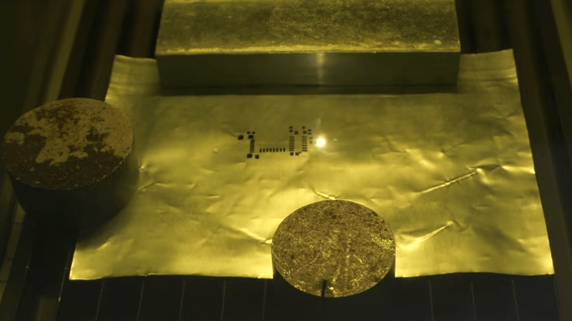
Solder stencils are a fantastic way to accurately apply solder paste to a PCB. Professionally-made stencils are cut from steel, but for the home hacker, soda cans continue to be the alternative of choice. The only trick is how to actually get those little holes made, and [Saheen Palayi] shows off both his method of laser-engraving the holes, as well as a tool for cutting the can in the first place.

Image
A good result starts with cutting a can cleanly, thanks to a 3D-printed tool.

To turn a soda can into a flat-ish aluminum sheet means cutting off the ends and slicing it open. Ideally, one achieves this without kinking or bending the thin metal. In practice, this is quite difficult. [Saheen]’s solution is something a little like a pipe cutter — a 3D printed tool that gradually presses a blade section from a utility knife into the empty can as it turns until it cuts through. Once the top and bottom are off, it’s easy enough to snip down the side to get a curved sheet.

The hole pattern comes from one’s PCB design software of choice, and the actual cutting is done by a fiber laser. The wavelength of fiber lasers makes them good at marking and cutting metal, and [Saheen]’s laser takes almost no time at all to cut the stencil into the thin metal.

Fiber lasers used to be the sort of tool that only industrial shops had, but they’re a prosumer-level tool that can be bought online nowadays. [Saheen] uses an xTool F1 Ultra to cut his solder stencil, and we’ve previously seen that same laser used to create a PCB by blasting away unwanted copper until only the traces remain.

We’ve seen aluminum cans etched and also machined to create stencils, and the laser is certainly the fastest. Watch it in action in the video below.

Continue reading “A Good DIY Solder Stencil Begins With A Cleanly-Sliced Soda Can” →
Image

Assembling And Testing A DIY Jet Turbine

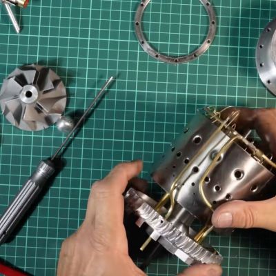
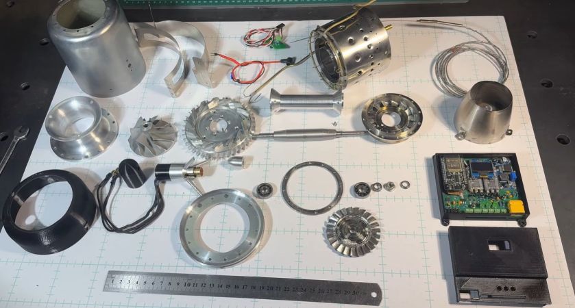
ImageAfter many months of painstaking work, [AlfMart CNC Garage] over at YouTube has finally reached the stage where he can fully assemble his DIY jet turbine and commence testing. Even if deceptively simple devices, just the starting mechanism turned out to be a challenge. Due to the extreme conditions that these jet turbines operate under, tolerances are narrow, and many of the materials require careful selecting and testing.

Fortunately this is not true for the outer casing, which is cobbled together from a commercial gas cylinder and a children’s steel drinking bottle that so happened to have the right dimensions. From there the parts get increasingly more specialized, down to the carefully balanced rotor. Assuming everything was done right up till this point, the first start-up will mean a happily roaring turbine and not a deafening explosion followed by a cloud of shrapnel.

In the video the full assembly can be observed, along with detailed instructions should anyone want to follow along with their own DIY jet turbine. Naturally a lot of attention has to be paid to tolerances during the assembly process. Following the basic turbine assembly, the RPM sensor circuit and the electrical starter are added, with the latter allowing for the turbine to spin up prior to ignition.

The first basic starter tests revealed an issue with the starter motor and clutch mechanism, requiring some upgrades. Before the first ignition the whole turbine has to be dynamically balanced, for which first a new balancing rig will be designed and assembled. While this means that first ignition will still be a while off, it’s best to take projects like this slow and steady. We’re also looking forward to seeing this new dynamic balancing rig that’s claimed to be much more advanced than that used for balancing the rotor.

Continue reading “Assembling And Testing A DIY Jet Turbine” →

Image

Easy Ways To Sink A Hardware Startup

[Ryan Walker] may have written up his observations a few years ago, but the lessons are just as relevant today as they were back then. He shares five easy ways to sink your hardware startup.

It’s a reminder that while hardware startups are unique, there are basic business realities that still apply because the hardware itself is going to be only one part of a whole. These business fundamentals can be a drag, but it’s worth giving them some attention. But if that’s not your jam, no worries. As [Ryan] experienced, they will explain themselves one way or another.

A good one is skipping market research. Do customers actually exist for this thing? Or forgoing market testing — do the customers actually want it enough to pay for it? One of the worst things to be stuck with is a product that everyone likes, but nobody wants to buy.

Premature optimization is another good one that a number of our readers can probably relate to in one way or another. It’s one thing to buy a tool or a part that one doesn’t end up needing, but when that gets scaled up it can put a real dent in a fledgling business’s development.

We’ve also shared insights on what it takes to develop a product and get it out there, whether as a solo entrepreneur or as part of a larger team, to help nudge the process toward success.

Image

Full-Color Looks Great On 3D Printed Sliding Puzzles

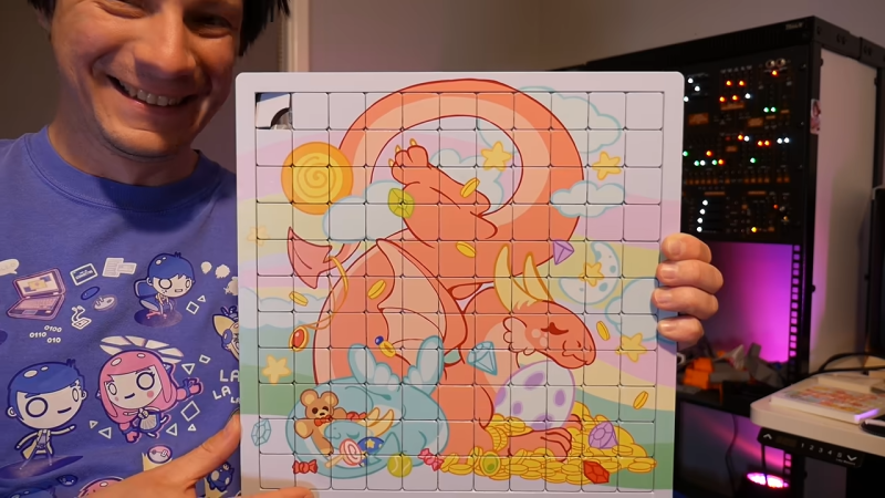
[Angus] of [Maker’s Muse] shows off both a parametric, print-in-place sliding puzzle design he created, and the results of UV printing full-color designs on the same. The results look beautiful, and there was a whole lot of trial and error involved in the process.

Image
The design includes a pop-out tile, which can be re-inserted to a finished puzzle.

Creating a good print-in-place sliding puzzle depends a lot on tolerances. Today’s 3D printers are much more capable in this regard than they were ten or so years ago, but getting the right feel to the pieces was still a long learning process. It’s not at all easy to get all the different characteristics in the right balance. On one hand, if the pieces are too tight they won’t slide easily. But if they are too loose, the puzzle can bind because the pieces have too much play. It may also flex enough to pop apart. And of course, the shape of the pieces and their mating surfaces are constrained to angles and shapes that 3D print reliably. [Angus] persevered and succeeded, and shows off everything from cute 3 x 3 units to a massive scaled-up 11 x 11 puzzle, printed on his Prusa XL.

Getting the color onto the print is the work of a desktop UV ink printer, the same model our own Tom Nardi had a hands-on look at last year. [Angus] shows how printing a single color image onto the puzzle is pretty easy and looks great, but what’s even better is a textured relief image with some real tactile depth to it. Expect a lot more work to do for that, because thick layers of ink gum the puzzle up with overspray unless one avoids printing over the gaps in the tiles.

Watch both the puzzles and the color printing in action in his video, embedded just below.

Continue reading “Full-Color Looks Great On 3D Printed Sliding Puzzles” →

Image

How To Fold Curved Lines In Metal Without Fancy Tools

Folding a sheet of metal in a straight line is one thing, but how does one fold multiple curved lines into a sheet of aluminum without fancy machines? [John] demonstrates how to do exactly that with little more than hand tools and a fair bit of patience. The secret is drilling a lot of small holes along each fold line.

Image
Complex shapes are possible with planning, hand tools, and patience.

First, a bit of background. [John] wanted to fabricate a curved piece of aluminum as cover that would match the sleek aerodynamic lines of a Belly Tank Lakester. The trick is that there isn’t a single straight line to be found, and the fold lines are all curves. How can one do such folding with only hand tools?

[John] found that fabrication was possible by drilling small holes all along each fold line, then carefully bending as needed. The line of holes weakens the metal, acting like a score line, and allow the required curves to be made cleanly. There’s some finishing work and straightening involved, but the hard part of making the actual folds is taken care of.

One method that didn’t work was cutting a shallow groove in the metal to create something like a pre-scored fold line. [John] tried this and found that while the metal does indeed fold along the weakened line, the aluminum tends to crack in the process. When making a line of holes instead, the metal between each hole bends nicely.

This technique does mean the finished part ends up with small perforations along each fold, but the part is mounted on the bottom of the car and [John] says that he’d have to look quite closely to notice. A little polishing goes a long way, too.

We have covered many ways to bend sheet metal and while machinery exists to do it exceedingly well, great results can be had with little more than simple tools and some patience.

Watch [John] go through the process in the video embedded below, or skip to 7:55 if you just want to see the end result.

Continue reading “How To Fold Curved Lines In Metal Without Fancy Tools” →

Image

Corners Lifting On 3D Prints? Guide Gives Prevention Tips

Large prints have a risk of warping, by which we mean corners can lift off the print bed as the object sort of curls inward on itself. It’s not always due to poor filament quality or an unclean build plate. Sound like something you’ve dealt with? Check out this handy roundup to understand why it happens, and learn ways to prevent it.

Image
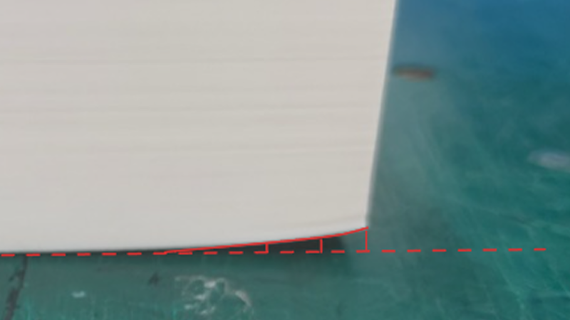
A big flat area with sharp corners is susceptible to warping. Breaking the footprint into a grid pattern helps distribute stresses instead of concentrating them at the corners.

The reason some objects have trouble while others don’t is physics. Deposited plastic shrinks ever so slightly as it cools, and some shapes — like wide, flat surfaces with sharp corners — are worse for this than others. This sort of problem is what the guide addresses with a number of techniques.

Some are simple, like turning on brims which increases an object’s footprint. This increased surface area offers more adhesion, but also increases heat transfer from the print bed into the model, slowing the cooling process. Thinner walls and an altered infill pattern is another option. Other techniques are more complex.

The most effective methods involve modifying the model itself to reduce or eliminate stress points. One such method is to break the model’s footprint into multiple zones with a shallow grid. Instead of one big flat bottom, the object has multiple smaller ones. Because big flat areas are more susceptible to warping than small ones, turning the bottom into a grid pattern helps spread those stresses out and prevent lifting.

If you design your own models, you’ll find several design tips worth keeping in mind. It’s always smart to practice good DFM (Design For Manufacturability) which means taking 3D printer strengths and weaknesses into account when designing an object. In this case, it can help prevent print failures. Good DFM can also make parts much, much stronger just by designing in the right features.

Image

Straight Talk On 3D Printing Footwear At Home

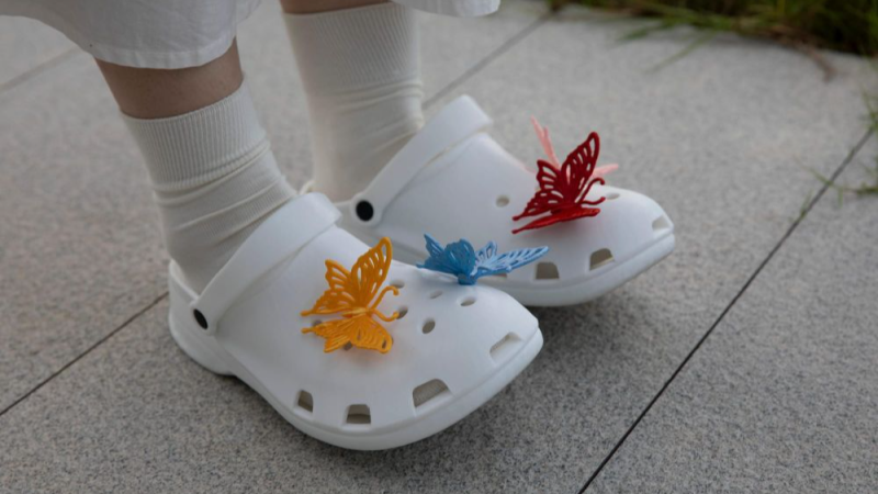
Printed footwear is an intriguing idea, but as far as projects go it is somewhat more complex than it first appears. This guide to 3D printing your own clogs not only provides a solid process, but also acts as a list of the challenges and pitfalls involved. After all, a piece of footwear is actually a fairly large object. Failed prints can be costly and time-consuming, so a guide like this is a valuable resource.

First of all, a 3D printer that can handle multi-material printing is called for. The footwear itself will be printed in TPU 90A as a sweet spot for hardness, but the print will require supports and those supports will need to peel away cleanly. The solution is a shoe printed in TPU with a rigid support structure of PLA. Using two different materials in the same print with anything remotely resembling efficiency calls for either a dual-nozzle print head, or a multi-toolhead printer.

Image
3D printing one’s own clogs can be rewarding, if not necessarily cost-effective.

Here we want to take a moment and say that while the guide itself suggests PETG is also a suitable support structure, we suspect this might only be true for the exact filament formulations used in the guide. The safer approach is to use PLA. Why? As we’ve seen in other tests, PETG has been observed to stick extremely well to flex filaments in general, whereas PLA doesn’t really want to stick to anything other than PLA. The exact formulations of TPU and PETG used in the guide might be compatible with one another, but in general we recommend sticking to PLA as a rigid support for flexible filament.

Assuming a capable printer and suitable materials are nailed down, one also needs to worry about keeping the TPU dry. It is very sensitive to moisture, which directly affects print quality. You’ll also need to dial in the settings — a gyroid-patterned infill of 15% provides the right amount of “squish”, which is most effectively fine-tuned by changing the infill pattern rather than the density.

Is it worth the time and effort and filament cost to print one’s own pair of slip-ons versus simply buying a pair of Crocs®? Maybe not, but it can still be rewarding and this guide will help minimize any failed prints in the process. And if you do get a nice print but the TPU is sticking a little too well to the build plate, reach for the isopropyl alcohol.