-
-
-
-
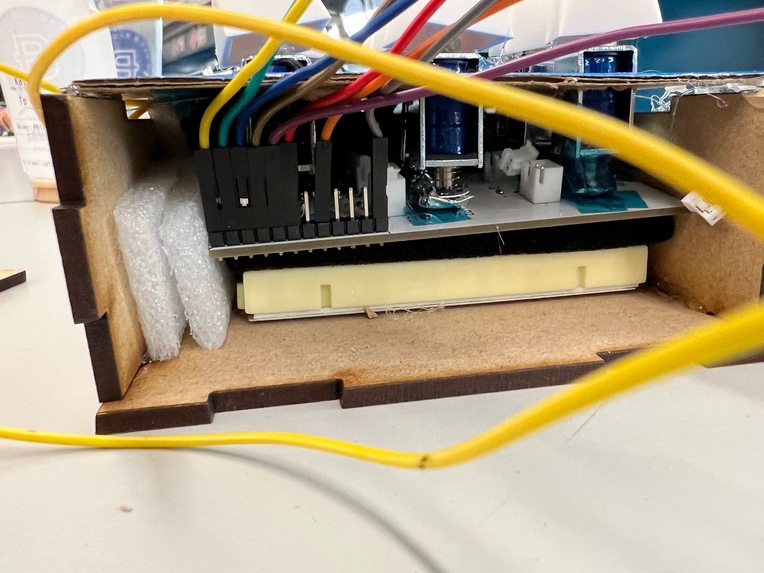
Cross-sectional view
-
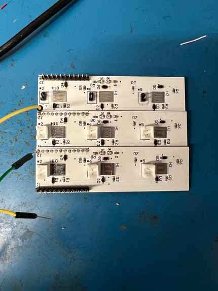
Keyboard PCB
-
PCB Modified with PMOS
-
-


Inspiration
Typing is a daily necessity. While trivial, people do tend to have different personal preferences for their keyboard pressure usually to fit the task they are completing or for personal comfort. By designing an ergonomic keyboard where users can change the actuation force of the keys, the keyboard users can complete work more efficiently and comfortably which could help boost productivity. There are a few different types of keyboard that deviate from the traditional keyboard design such as a hall effect keyboard that allows the user to change the actuation force needed for a key click signal to be registered. However, we are approaching this need in a different way where actual “clickiness” (for lack of a better word) of the keys change depending on how much the user tunes it (ex: after being tuned, the keys are now harder to press down or when tuned in opposite way the keys are now really easy to click). The intended purpose is so that users don't have to buy multiple keyboards for different tasks and different moods, especially when their fingers get tired after a long day of work.
What it does
We are looking to design an ergonomic keyboard where users can change the actuation force of the keys. This will be achieved by controlling push-pull actuators under each key cap with different voltage levels such that the amount of force required to push the actuator downwards and register the key-press differ based on the preset voltages. By allowing the user to change this force through a change in electrical voltage, it makes for a customizable keyboard where the keys can be adjusted to the user’s habits and changing preferences.
How we built it
Push-Pull Solenoid Actuators as Keys
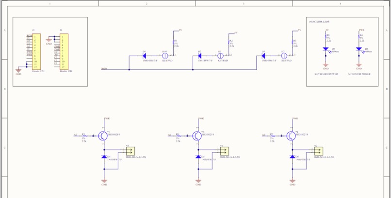
We started by purchasing a singular push-pull actuator from Adafruit to test our hypothesis about the relationship on variation in voltage and actuation force. After setting up the circuit using diagrams we found online, we were able to successfully control a singular actuator and reproduce results similar to what we desired. We then decided to copy this schematic / layout 9 more times on our PCB.
Ultrasonic Distance Sensor
As we were testing our push-pull solenoids, we realized that the solenoids' bodies tend to over-heat if it is powered for a long period of time, so we also added an addition ultrasonic distance sensor that sends a signal to a pMOS, such that the actuators for the keys are only powered if the ultrasonic sensor detects an object (user's) had within its proximity.
Keyboard Matrix
Our keyboard matrix consists of 3 rows and 3 columns, all of which are pulled high. The Arduino outputs to every row by quickly turning off a singular row, while the columns remain as inputs such that when a button is pressed, the column becomes low. This means that, in our code, whenever we see a column and a row both equaling 0, we would output / print the corresponding event for a button press. Note that, each column is initially pulled high (when no keys are pressed) using a pull up resistor and is then pulled “low” when a solenoid is pressed down, tying the column signal to GND. To accomplish this, we have attached a little aluminium sheet underneath each of the solenoids, which when pressed would bridge the two pads on the PCB's key foot-print.
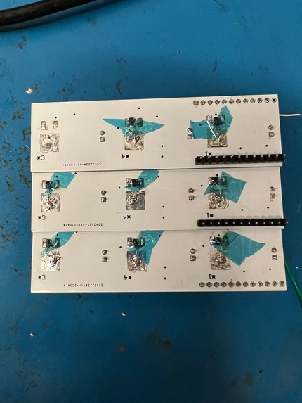
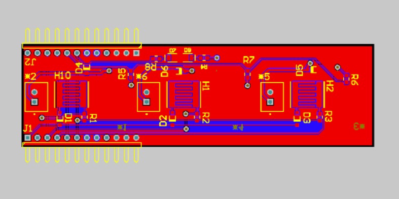
Printed Circuit Board (PCB)
We have a custom PCB for each row of the keyboard. Three individual row PCBs are then soldered together to form a keyboard with 9 keys. Each row-based PCB has essentially 2 circuits on the singular board: a circuit that powers and controls the actuators and another that detects when a key is “pressed” and interfacing with the Arduino Uno / Leonardo. After receiving our PCBs, we soldered all of the components on the board by hand.
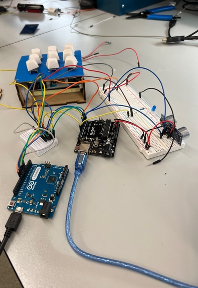
Communication and Overall Structure of Project
Between each row-based PCB, we added connectors on both the top and bottom of the PCB such that each row can communicate with each other and so that we would only have to have one PCB that actually have connectors to the MCU. From there, the Arduino Uno sends out the switching row signals as previously mentioned and is also responsible for detecting when the keyboard should be on by operating the ultrasonic sensor; on the other hand, the Leonardo detects both the row and column signals as inputs and output the appropriate key event as a HID such that users can perform the short cuts on Altium that they desire.
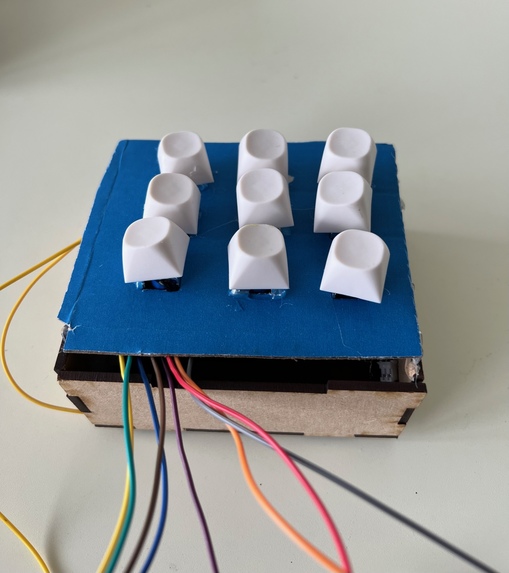
Assembly
Lastly, to secure the solenoids in place, we have a wooden enclosure along with a cardboard top to put everything together. We also purchased actual keycaps which we placed on top of the solenoids to simulate for a more keyboard-like experience.
Challenges we ran into
Current Draw of Actuators
As previously mentioned, each solenoid would draw approximately 0.3-0.5 amps depending on the voltage that we have set it to, which meant that even supplying power to just 9 keys would require 2.7 - 4.5 amps 😬. That completely detracted us from wanting to have a potentiometer set up which allows users to personally dial the voltage supplied to the actuators (which corresponds to the change in keypress forces). After communicating with the teaching team, we ultimately decided to hook the connections directly to the power supply such that we can reach our desired current rating (we also only had 6 actuators plugged in for demonstration purposes to cap the current at less than 3 amps.
Keyboard Matrix
To register the actual key-press events, we initially wanted to simply treat each key as a button and have an ISR in our code for key-press detection. However, we ran into the issue that our Arduino Uno board will not have enough input pins for each key, and so we decided to implement a keyboard matrix. Through research, we found this helpful link: https://electronics.stackexchange.com/questions/562412/4x4-keyboard-matrix-why-no-pull-down-resistors and decided to recreate something similar.
HID Programming
Programming the Arduino Leonardo for HID and allowing it to simulate keypress events on the computer was no easy task either! Although we quickly found a library that seems reliable (from Arduino), the first difficulty we ran to was actually flashing code onto the Leonardo via Microchip Studio as the Leonardo required a boot loading process before the actual code can be flashed. After trying to write a Python script for the boot loader for many hours, we ultimately decided to just use a Mac and CLion as that would automatically flash the boatload process for us. The second issue we ran into was indeed trying to use a C++ based library with our bare-metal C programming. Yet even after successfully writing a C++ wrapper for the library, it was still not working as the Leonardo actually required another piece of code for it to be first recognized as a USB input device for HID by the computer. Luckily, with the help of the teaching staff (shout out to Will), we were able to find another library that included the previous process as part of its code base and successfully recreate keypress events that we desire.
PCB Manufacturing
Issues arose as we started soldering and testing our PCB too. The main problem we ran into relates to the actuator control circuit. Our design intially uses an NPN Transistor with the base contorlled by an arduino output and the collector connected to a power supply to supply the "high" current and allow the voltage to vary. However, after soldering, we realised that since we had connected the load (actuator) to the emitter of the transistor, the voltage being supplied to the actuator would alywas be the voltage of the arduino output minus the voltage drop across the diode (0.7V). This would completely defeat the purpose of having a keyboard that changes in clicky-ness when voltage is varied.
After discussing with an upper classman, we came to the conclusion that switching the transistor to a PMOS would be the best choice. By using a PMOS, when the arduino pulls the gate low, the PMOS would turn on and the voltage from the source (connected to power supply) would be the voltage supplied to the actuator (minus some small voltage drop). We were also able to find a PMOS (IRLML6401TRPBF) that could tolerate 4.3A. The footprint of the PMOS was different from the footprint of the NPN we had chosen for the PCB so we had to jumper wire the connections and use kapton tape to ensure that the jumper wires would not short if they were accidentally flattened. Furthermore, we faced issues such as inaccuracies in soldering and other factors that we could not pinpoint, which resulted in us having to solder an extra PCB to ensure that we have everything working.
Accomplishments that we're proud of
Firstly, we are very proud of the fact that our product actually works. Taking feedback from fellow Altium users, we have implemented shortcuts such as DI, TGA, TDR, and even the numeric * for users to have an easier time in designing PCBs with Altium. Furthermore, we believe that designing and also assembling our own PCB was a great accomplishment too - especially along with the things that we had to debug to have it fully functional. Lastly, we are super glad that our code works and we were able to accomplish our goal and program both the Arduino Uno and Leonardo in bare metal C.
What we learned
From the software perspective, I believe the biggest thing that we learned was how to use C++ libraries and incorporate it into bare metal C programming as this allows us to have much more functionalities that we can perform on the Arduino MCUs. Furthermore, writing a wrapper for the C++ library required us to understand essentially which parts of the library we need and how we would actually present / export the library to a C language compiler, all of which took a lot of research and trial and error. Lastly, we also have a better understanding of the overall HID workflow now as many issues arose when we were configuring the Leonardo to perform in our desired manner.
From a hardware perspective, the biggest things we learned was in regards to debugging the NPN transistor. For example, we have now learned that the voltage at the emitter is equivalent to the voltage at the base - 0.7V. Therefore, to use the NPN transistor in a configuration that would operate the way we wanted (being able to vary voltage while still using the property of a transistor to supply a lot of current) the load should have been across the collector instead of the emitter. Furthermore, a NMOS would have also been a good choice, since with an NMOS was used instead of a PMOS, it makes the coding more intuitive and saves more power as 0v at the gate would turn the NMOS off instead of having to constantly supply 5V to the gate if we wanted to keep the actuators off.
What's next for ClicK.E
There are many improvements that we still want to make to ClicK.E. Firstly, we want to replace the cardboard top casing with a more rigid cover so the solenoids will not “cave in” as time goes by - this would allow for higher reliability of our product. Furthermore, we would also like to replace the aluminum sheets that help pull each column low with something more reliable and professional, such as the capacitive materials used under the number pads of calculators.
We would also like to find alternatives to the actuators as actuators themselves draw way too much current. Some of our current thoughts include using PWM (which the user can tune) to control electric motors that is then attached to a gear and rod system, as depicted here: 
Lastly, one of our more ambitious goals would be to make this into an actual keyboard instead of just a keypad (although this definitely requires us to first resolve the actuator current draw issue).
Built With
- arduino-leonardo
- arduino-uno
- c

Log in or sign up for Devpost to join the conversation.