-
-

-
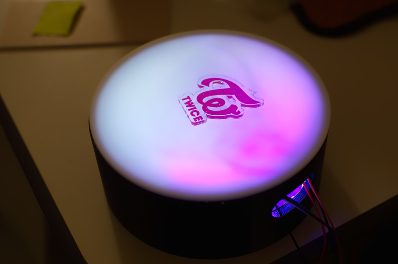
Product Image


Inspiration
Have you ever wanted to transform your room into a karaoke bar and sing the night away? With KaraBong! you can! This project will enable you to live out your idol dreams in the comfort of your own room. This microphone that takes in voice signals, amplifies it with autotuned (turn on or off) output through a speaker. In addition, the microphone will interact with LEDs. Their brightness will depend on input wave amplitude and the color is mapped to frequency. In autotune mode the LED colors would change in a discrete fashion.
What it does
The KaraBong! is a fun karaoke mic to help us serenade our roommates. The goal is to create a microphone with reactive lights and different amplification modes to simply have a fun time!
How we built it
The final prototype was constructed using a 3D printed shell, along with laser cut acrylic parts. All of the electronics fit onto an Arduino breadboard shield, which is housed inside the head of the microphone. The microphone is connected through a low pass filter into the Arduino's ADC pin. The Arduino then measures the amplitude and frequency of the incoming wave. The frequency of the wave is mapped to specific colors for the LEDs, with lower frequencies mapped to a pinker color and higher frequencies to apricot. The LED values are normalized such that they always sum to the same total RGB value in an attempt to make the brightness uniform. In reality, humans are more sensitive to green, which makes the apricot appear brighter. The amplitude is used as a scaling factor for all of the RGB values. This effectively makes larger amplitudes the same color, but just brighter. To control the speaker, a PWM pin is sent through a coupling capacitor into an audio amplifier circuit with the primary chip being an LM386. The output of that chip is connected to a 4Ω speaker.
Course Concept: PWM, ADC, Analog Signal Processing, Interrupts
Challenges we ran into
Major challenges breakdown into three categories: noise, analog design, and LED control.
The microphone's output waves were inherently noisy, which made both analog amplification and frequency measure challenging. In an attempt to mitigate high frequency noise, multiple iterations of different low pass filters were put into place, however all were either attenuated the desired signal too much or allowed too much noise to pass which greatly affected frequency measure. Eventually, a mixture of filtering and software techniques were used in order to get relatively accurate frequency measure. However, no full analog solution was found, so purely analog amplification was ultimately removed from the project.
Initially I intended to design an analog amplifier for the microphone from op-amps and transistors. After many iterations, I was somewhat successful, with a design with multiple amplifying and buffering op-amps, low pass filters for "clean" amplification and a CD-amp to drive the speaker. However, this solution simply did not amplify the signal enough and the amplification sounded very low quality. Eventually a dedicated LM386 chip was used in its place, which proved to be much more successful.
Initially I thought controlling the LED strip would be accomplished by 3 PWM signals for each R, G, and B. However, this was not the case. After reading the data sheet for the WS2812B light strip, I learned that the RGB value for each LED is controlled by its own microcontroller that communicates with the Arduino via an NRZ SPI protocol. After initial (failed) attempts at sending signals via interrupts, I found that most LED strip libraries use assembly instructions and ASM manipulation in order to send the precise timings. As a student who has never encountered assembly, I decided to use the library instead, which made everything easier.
Accomplishments that we're proud of
I'm proud that frequency measure finally worked, as this issue was fairly pressing for several days. I'm also proud of getting my voice to come through on a buzzer using my initial audio amplifier circuit - although it sounded very bad, I felt like Alexander Graham Bell when I finally heard sound out of the buzzer.
What we learned
I learned that despite my efforts to apply my ESE319 knowledge, specifically designed audio amplifier chips will outperform my efforts. I also learned that it is important to use both software and hardware solutions to solve a problem from essentially both ends.
What's next for KaraBong!
Future steps would be to design a power system for the whole system to make it portable. We have already investigated using a boost converter, similar to a MintyBoost. However testing with the MintyBoost caused strange behavior with the Arduino, likely due to the current draw of both the LED strip and speaker, which very likely exceeded the 500mA maximum of the MintyBoost. In addition, assembling a final, smaller microphone would be ideal, with a soldered PCB. In addition, further refinement of the frequency to OCR2A function would be good, since currently it is the most accurate around 440 Hz and drops off at both higher and lower frequencies. In addition, I would like to further investigate how to more cleanly record the analog microphone data, so that analog amplification can be possible.
Built With
- adc
- atmega328p
- c
- pwm

Log in or sign up for Devpost to join the conversation.