
OUTLINE
- Basics
- Materials
- Nomenclature
- Drawing Conventions
- Conclusions
COMPOSITE BASICS
FIGURE 1

- Composites generally come in one of two forms: – Cloth or Fabric: a woven material with fibers usually running in both 0° and 90° orientations – Unidirectional fiber (a.k.a.: Uni or Tape) fibers all run in the same direction
- Laminates (multiple plies) are constructed from a combination of lamina(single ply)
- Sandwich panels are constructed from a combination of laminates, core, and typically a film adhesive
CLOTH VERSUS UNIDIRECTIONAL
CLOTH
Advantages
- Drapes very well
- Easier to layup over complicated geometry
- Strength in two directions
- Bonds slightly better than uni
Disadvantages
- More expensive than uni
- Lower properties due to the fact fibers have to travel out-of-plane (over and under) due to the weaving process
UNIDIRECTIONAL
Advantages
- Better directional in-plane properties
- Less expensive than cloth
- Can easily tailor properties (i.e. strength, stiffness) in the needed direction
Disadvantages
- Hard to lay up over difficult geometry or complex curvature
- Requires careful planning to handle bearing loads
- May require longer lay up time to achieve desired thicknesses (uni is generally thinner than cloth)
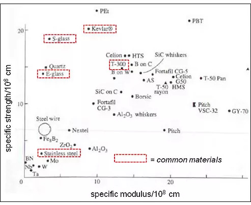
ROUGH ORDER OF MAGNITUDE FIBER COMPARISON
Specific Modulus is a materials property consisting of the elastic modulus per mass density of a material. The specific modulus is often important in aerospace applications in which maximum stiffeness for minimum weight is required.
Specific Strength is a material strength divided by its density. It is expressed in newton metres per kilogram, and is used for tensile strength as for compressive strength. It is sometimes known as the strength-to-weight ratio. Materials with very high specific strengths are widely used in aerospace applications where weight savings are more important than material costs.
FIGURE 2
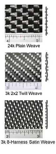
COMMON CLOTH WEAVES
There are many weaves available and these are just a few common examples
3k fiber is common, however 12k+ may be cheaper or have additional cosmetic appeal
FIGURE 3
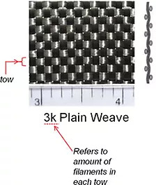
FIGURE 4
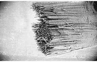
CARBON TOW MAGNIFICATION
FIGURE 5
Typical densities for weight calculations
FIGURE 6
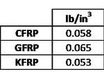
Design Trick: if adhesive is not being calculated separately add about 10% to the listed densities for the overall structure
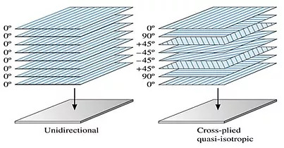
BASIC LAMINATE STACKING
Laminate stacking and ply orientation is specific to the application.’
FIGURE 7
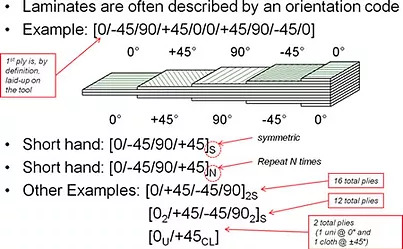
COMPOSITE LAYUP NOMENCLATURE
FIGURE 8
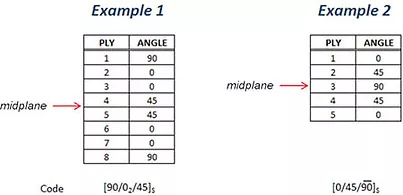
SYMMETRIC LAMINATES
Laminates possessing symmetry of lamina orientations about the geometric midplane
FIGURE 9
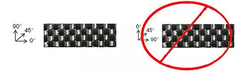
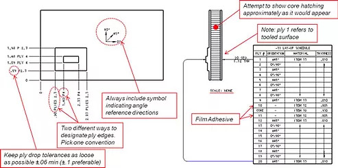
COMPOSITE DRAWING CONVENTIONS
The goal of composite drawings is to be as clear as possible – leave as little to misinterpretation as possible
Usually the 0° direction is along the long axis of the part
FIGURE 10
For simple lay-ups ply drops can be shown as below
FIGURE 11
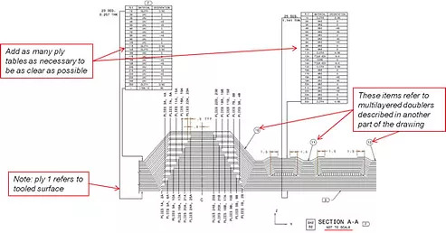
More complicated lay-ups may require more detailed descriptions
FIGURE 12
CONCLUSION
Composite design and analysis requires a strong understanding of the material behavior, design practices, and manufacturing capabilities. The scope of this presentation scratches the surface of composites and their applications but we hope it sheds light on some of its mystery. Quartus Engineering Incorporated hopes you found this information useful in addressing your engineering challenges.