-
-
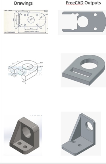
Examples for the CAD outputs depending on the input as drawing

Protolab: Turn 2D Engineering Drawings into 3D Models
Inspiration
Protolab began with a conversation with my co-worker, Dean, about improving an engineering-drawing annotation tool.
Many companies still rely on legacy 2D drawings. These drawings may contain enough information to manufacture a part, but converting them into editable 3D CAD is slow, repetitive, and dependent on skilled engineers.
Existing vision tools can identify dimensions and labels, but annotations alone do not produce a usable engineering model. We wanted to create a more productive workflow that could:
- understand a drawing;
- organize its engineering evidence;
- propose a CAD feature plan;
- generate real 3D geometry;
- show which source information supported each decision.
I started with caid-technologies/CAD-Annotator, which already supported drawing uploads, vision-based annotation extraction, and bounding-box visualization.
My Build Week goal was to extend it from an annotation tool into an end-to-end drawing-to-CAD workflow.
The core question became:
Can AI reduce the manual work of reconstructing CAD while remaining honest about what the drawing does—and does not—prove?
What I built
Protolab converts a rasterized engineering drawing into an evidence-backed parametric model and a validated ISO 10303 STEP file.
Instead of manually rereading dimensions and rebuilding every feature, an engineer can upload a drawing and receive:
- extracted dimensions, annotations, and drawing views;
- a structured reconstruction plan;
- traceable links between CAD parameters and source evidence;
- confirmed, inferred, and unresolved values clearly separated;
- editable 3D geometry;
- a validated STEP file for continued engineering work.
The system analyzes both the full drawing and overlapping high-resolution regions so small dimensions remain readable. It reconciles duplicate observations, groups multiple views of the same part, and identifies when a drawing contains separate physical bodies.
It supports common operations such as profiles, lines, arcs, circles, extrusions, cuts, holes, patterns, revolutions, fillets, and chamfers.
Before export, Protolab checks whether the proposed geometry is valid. It reports properties including solid count, bounding boxes, volume, surface area, center of mass, and contact or interference between bodies.
The goal is not to remove engineers from the process. It is to reduce repetitive reconstruction work and give them a faster, more transparent starting point.
How I built it
I approached the problem as a hybrid AI and deterministic geometry system.
The vision model is responsible for interpreting the drawing: recognizing views, reading annotations, associating dimensions with features, and proposing a reconstruction plan. Conventional code is responsible for coordinate transforms, schema validation, feature execution, physical checks, and STEP export. This creates an intentional boundary between what the model believes it sees and what the CAD engine can actually build and verify.
For tiled analysis, an annotation at tile-local coordinates ((x_t,y_t)) is mapped back to the full drawing using the tile offset ((o_x,o_y)):
$$ x_g = x_t + o_x, \qquad y_g = y_t + o_y $$
Overlapping tiles improve small-text recognition, but they can produce repeated observations. Those observations are normalized and compared using their labels, values, view membership, spatial distance, and bounding-box overlap. A common overlap measure is intersection over union:
$$ \operatorname{IoU}(A,B) = \frac{|A \cap B|}{|A \cup B|} $$
Likely duplicates are merged deterministically while their source-tile provenance and confidence are retained.
The model output is not sent directly to the geometry kernel. It first passes through a versioned geometry contract that checks positive dimensions, supported operations, item references, transforms, base-feature compatibility, and evidence status. Geometry is then built as an ordered feature history. Conceptually, the result is:
$$ S_n = f_n!\left(f_{n-1}!\left(\dots f_2(f_1(S_0))\right)\right) $$
where (S_0) is the initial profile or solid and each (f_i) is a validated CAD operation such as an extrusion, cut, fillet, or chamfer.
I used GPT-5.6 for hosted drawing interpretation and reconstruction planning, while keeping the API key and model calls on the server. I also added a local vision path for private analysis. The final STEP conversion happens locally, and invalid model output is rejected or returned for correction rather than silently converted into partial geometry.
Codex accelerated the work by helping me inspect the upstream project, understand its architecture, design the reconstruction contract, implement and debug the TypeScript and browser workflow, generalize the Python geometry executor, create focused tests and fixtures, diagnose native CAD dependency issues, and verify that the exported files contain real OpenCASCADE STEP geometry.
The core product decisions remained human-directed: choosing the engineering problem with Dean, limiting the supported geometry, requiring evidence and confidence, keeping separate bodies separate, and refusing to present inferred dimensions as manufacturing truth.
Challenges I faced
1. Curved geometry is much harder than it appears
Curved parts were the largest interpretation challenge. A raster image can show an arc, rounded end, fillet, concentric opening, or perspective-distorted circle without clearly revealing its construction. The model may recognize that a boundary is curved but still confuse the radius, center, tangent relationship, or whether the curve is additive or subtractive.
For a circle, a few noisy pixels can significantly affect the inferred parameters:
$$ (x-a)^2 + (y-b)^2 = r^2 $$
If ((a,b)) or (r) is not explicitly dimensioned, many different valid circles can resemble the same rasterized curve. Perspective and line thickness make the ambiguity worse. The solution was not to pretend that the model had recovered exact geometry. I expanded the operation vocabulary gradually, added dimension and topology checks, created targeted fixtures for arc-based parts, and marked unsupported or inferred values for review.
2. Even 2D drawings require extensive iteration
At first, the problem seemed simpler because the input was “only” a 2D technical drawing. In practice, reliable interpretation required repeated prompt refinement, examples, evaluation cases, schema constraints, and deterministic post-processing. This was closer to training a workflow than asking a model a single question.
Engineering drawings contain borders, extension lines, centerlines, section marks, hidden lines, multiple scales, repeated views, and dimensions that may apply to geometry far from their printed position. The system had to learn, through iterative evaluation and explicit rules, which lines describe the part and which lines only describe the drawing.
3. Multiple views are not multiple parts
Front, top, side, section, and detail views often describe the same physical body. A naïve pipeline can create one solid per view or interpret a detail view as a separate component. I added view grouping and body-decomposition rules so that orthographic views reinforce one reconstruction while visible seams, joints, material changes, and motion boundaries can indicate separate manufactured bodies.
4. Missing dimensions create an unavoidable truth boundary
A single image does not uniquely determine hidden geometry, thickness, material, tolerances, fit, or design intent. There is no algorithm that can recover information that was never present in the drawing.
This forced an important product decision: distinguish transcribed dimensions from inferred estimates and expose unresolved requirements instead of inventing plausible manufacturing values. A structurally valid STEP file proves that the proposed geometry can be built; it does not prove that every inferred parameter matches the designer's intent.
5. Model output had to become executable without becoming trusted
Vision-language models can return malformed JSON, truncated responses, unsupported operations, inconsistent units, impossible radii, zero-sized solids, or holes outside the owning face. Generating syntactically valid JSON was not enough.
I added strict schemas, compact retry paths, explicit units, bounded operations, dimension ledgers, geometric preconditions, and a correction pass that receives the exact validation failures. This made failures visible and actionable while preventing invalid plans from reaching the CAD kernel.
6. CAD dependencies and export validation are real engineering work
Producing a file named .step is easy; producing a valid solid through a real geometry kernel is not. CadQuery, OpenCASCADE, and FreeCAD introduce native dependencies and environment-specific behavior. I had to diagnose installation and command-line execution issues, support practical fallback paths, inspect exported files, and test actual geometric properties rather than trusting a successful process exit.
7. A reproducible demo needs more than a successful golden run
The golden bracket result proved the pipeline, but a Build Week submission also needs a bundled input, stable setup instructions, repeatable output, clear limitations, and a short demonstration that viewers can understand. Preparing fixtures and validation reports was essential for showing that the result was produced by the workflow rather than handcrafted for the video.
What I learned
The strongest AI productivity tools do not simply generate outputs. They reduce repetitive work while making results easier to review and trust.
Protolab works best when AI handles interpretation and planning, while deterministic software handles geometry, validation, and export.
The main lessons were:
- A smaller, reliable set of CAD operations is more useful than broad but unpredictable support.
- Engineers need source evidence, not confidence scores alone.
- Valid geometry and accurate reconstruction are different claims.
- Multi-stage workflows are more dependable than asking one model to do everything.
- Precise validation errors help both the model and the engineer correct problems faster.
- Local processing matters for confidential engineering drawings.
- Uncertainty should be visible rather than hidden behind a polished result.
Why it is different
Most drawing-analysis tools stop after extracting text, dimensions, or annotations. Protolab connects that information to an executable CAD workflow.
It preserves four separate layers:
- what is visible in the drawing;
- how the model interprets it;
- what the geometry engine can build;
- what still requires engineering review.
Each generated parameter can record its value, unit, role, supporting evidence, confidence, owning body, and whether it is confirmed or inferred.
This makes the result more than a generated 3D shape. It becomes an auditable engineering proposal that a person can review, correct, and continue working from.
Work and productivity impact
Reconstructing CAD from legacy drawings is valuable but time-consuming work. Engineers must search for dimensions, compare views, recreate feature histories, check assumptions, and validate the resulting solids.
Protolab brings these steps into one workflow.
It can help engineering teams:
- convert old drawings into usable digital models faster;
- reduce repetitive CAD reconstruction;
- review extracted dimensions in one place;
- find missing or contradictory information earlier;
- preserve links between source drawings and generated geometry;
- create a starting model without hiding uncertainty;
- keep sensitive files local when required.
This is especially useful for manufacturing teams, repair operations, suppliers, hardware startups, and organizations modernizing archives of legacy drawings.
Origin and contribution
Protolab builds on Dean Hu’s ideation and the foundation of caid-technologies/CAD-Annotator.
The original project provided drawing upload, vision-based annotation extraction, bounding-box visualization, and GD&T and design-for-manufacturing analysis.
My Build Week work extended it with:
- full-drawing and high-resolution regional analysis;
- coordinate reconciliation and deduplication;
- confidence and source provenance;
- an evidence-backed geometry contract;
- multi-view and multi-body reconstruction;
- confirmed-versus-inferred dimension tracking;
- CadQuery, OpenCASCADE, and FreeCAD execution;
- geometry and interference validation;
- real STEP export;
- tests, fixtures, and a dedicated review workflow.
Current status and next steps
The reference bracket workflow generates a valid STEP file through OpenCASCADE. The system also supports a broader range of prismatic, revolved, curved, and multi-body examples.
Next, I plan to improve curved-geometry evaluation, uncertainty visualization, cross-view contradiction detection, and support for PDF, DWG, and DXF inputs.
The long-term goal is not “one image in, perfect CAD out.”
It is a trustworthy productivity tool that reduces reconstruction time, shows its work, and tells engineers when human judgment is still required.
Built With
- cadquery
- codex
- gpt-5.6
- javascript
- node.js
- openai
- opencascade
- python
- react
- sharp
- typescript


Log in or sign up for Devpost to join the conversation.