Arduino Interface ADC
What is ADC?
- ADC (Analog-to-Digital Converter) converts an analog signal (voltage) into a digital value.
- Arduino boards (like UNO, Nano, Mega) have an inbuilt 10-bit ADC.
- 10-bit = 2¹⁰ = 0–1023 values.
- Reference voltage = 5V (default on UNO).
- So, each step ≈ 5V / 1024 ≈ 4.88 mV resolution.
Arduino ADC Pins
- On Arduino UNO, analog input pins are labeled as A0–A5.
- These can read voltage from 0 to 5V.
Real-world Use of ADC in Arduino
- Temperature sensors (LM35, TMP36).
- Light sensors (LDR).
- Gas sensors (MQ series).
- Sound sensors (microphone).
- Voltage monitoring in battery systems.
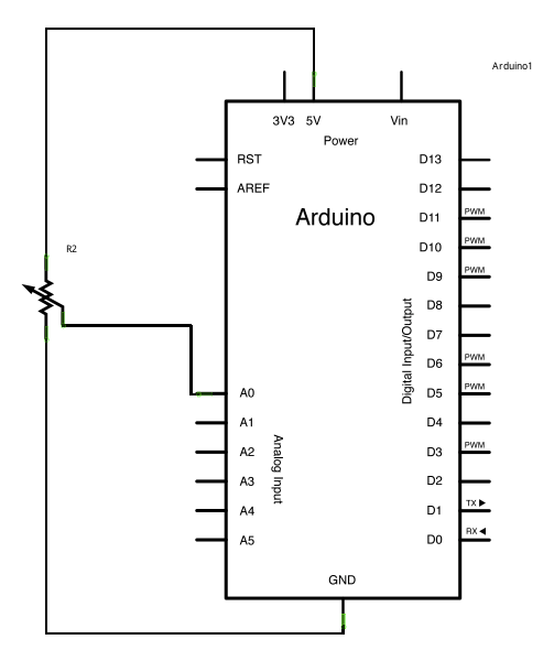
Circuit for Arduino Interface ADC

Arduino Interface ADC Schematic
Read ADC Value and print in (UART) Serial
Code
//www.aruneworld.com

int potPin = 0;

void setup()
{
  Serial.begin(9600);
}

void loop()
{
  int reading  = analogRead(potPin);
  Serial.println(reading);
  delay(500);
}
Line by Line Explanation
int potPin = 0;potPinis assigned to analog pin A0.- In Arduino,
0means A0,1means A1, and so on.
void setup()- Runs once when Arduino starts.
Serial.begin(9600);initializes Serial Communication with the PC at 9600 bits per second.- Needed to print data on Serial Monitor.
void loop()- Repeats forever.
int reading = analogRead(potPin);- Reads the analog voltage (0–5V) at pin A0.
- Converts it to a 10-bit digital value between 0 and 1023.
- 0 → 0V
- 512 → ~2.5V
- 1023 → ~5V
Serial.println(reading);- Prints the numeric value to the Serial Monitor on your PC.
delay(500);- Waits 500 ms before the next reading.
- So you see 2 readings per second.
Circuit Setup
- Use a potentiometer (10kΩ):
- One side → 5V
- Other side → GND
- Middle pin → A0 (analog input)
Example Output (Serial Monitor)
If you rotate the potentiometer:
0
120
350
700
1023
(Values change based on position of knob).