Summary of Arduino Self Balancing Robot
This project details the construction of a self-balancing robot using an Arduino microcontroller. It involves building a mechanical frame from plexiglass plates connected with screw rods and nuts, powered by two 6V DC motors with wheels. The electronics include an Arduino (Uno or Mega), an L298 motor driver, a LiPo battery, three potentiometers for tuning PID control parameters, and an MPU6050 gyroscope sensor to maintain balance. The motors are controlled synchronously using a dedicated library to ensure precise motion and balance adjustments.
Parts used in the Self Balancing Robot:
- Arduino Uno or Mega
- L298 Motor Driver Card
- 3 potentiometers
- Plexiglass plates (20 × 8 cm)
- 4 screw rods (about 20 cm length)
- 24 nuts
- 2 pieces 6V DC motors (250 rpm) with wheels
- LiPo battery (12V)
- MPU6050 gyro sensor
- Iron wire and silicone wire for mounting
In this project I will describe the construction of robots standing in equilibrium with Arduino.We explained in our previous version of the android controlled project. In this project we will move to our control. Let’s go let’s get to our building project.
Step 1: Materials:
- Arduino Uno or Mega
- L298 Motor Driver Card
- 3 Piece potentiometer
- You can cut plexiglass plate for mechanical or rigid plastic containers.
- 4 pieces of screw rods in length of about 20 cm
- 24-Piece Nut
- 2 pieces 6V DC motors at 250 rpm (from which together with the wheels)
- Lipo battery
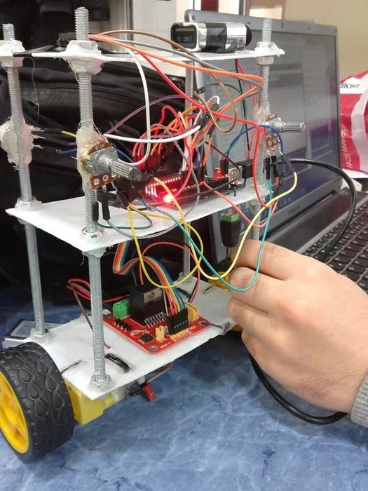
Step 2: The Mechanics:
20 × 8 cm three plexiglass plate final.You can cut in different sizes. Cut diameter of the screw rod through the hole until after the corner of each sheet’s open. Each plate so that the rod between two nuts and bolts Let’s mounting screws. Let us consider each other to be equal to the gap between the plates. The engine then our way to the bottom right and left sides of the plate will be located right in the center of iron wire tied to my silikonlayal. Such mechanical parts.
Step 3: Electronic Section:

We use the engine running in a synchronous motor drive with its own library.In this way, also it happens to be that minimize errors in the work of the engine with full data system.
We’re putting the plus side of the battery to the motor LiPo 12V power input on the drive. We’re putting the minus end of the GND input.
In addition to the circuit attribute to 3 units 0.1 analog potentiometer year and 2 pins.Here the task of potentiometer kPa, manually adjusting the values of kd and will allow us to find the optimal balance point of the robot.Mpu6050 gyro sensor mounted on the bottom plate horizontally let.
Read more: Arduino Self Balancing Robot