Summary of Build A Cheapest Possible Arduino-Robot
This article guides building the cheapest possible Arduino robot using basic components. It covers installing the Arduino IDE, uploading a blinking LED example sketch, and connecting an IR distance sensor (Sharp GP2Y0A21YK0F) to measure distances from 10cm to 80cm. The sensor is connected to the Arduino’s 5V, GND, and analog pin A0, with calibration done via a lookup table in the code. Users learn to read sensor values through the Serial Monitor and adjust for accuracy, forming a foundation for creating a simple Arduino robot.
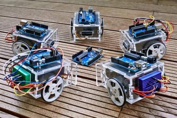
Parts used in the Cheapest Possible Arduino-Robot:
- Arduino UNO R3
- USB cable
- Mini solderless breadboard
- IR sensor (Sharp GP2Y0A21YK0F)
- Continuous rotation servo x2
- Battery holder
- AA batteries x4
- Color wires
The aim is to build cheapest possible Arduino-robot
Step 1: Components
- Arduino UNO R3 x1
- USB cable x1
- Mini solderless breadboard x1
- IR sensor x1
- Continuous rotation servo x2
- Battery holder x1
- AA battery x4
- Bunch of color wires
Step 2: Getting Started With Arduino IDE
First of all we need to install Arduino IDE. The Getting Started Guide from the official Arduino website will tell you everything about it. Once you have installed Arduino IDE you can start writing your own programs for Arduino (often called sketches). We’ll use a language based on C to program our Arduino.
Let’s start.
- Open Arduino IDE. By default it will show an empty sketch.
- Open example sketch via *File → Examples → 01.Basics → Blink* (or see [Appendix 1](#appendix-1-led-blinking-example)).
- Compile this example (*Sketch → Verify/Compile*). You’ll see “Done compiling” and the size of the binary in bytes when the compilation is completed.
- Connect your Arduino board to your laptop using a USB cable. After that you will see some connected device in *Tools → Serial Port*. Select it. Now you are able to upload your sketch to the Arduino board.
- To start uploading simply press the Upload button on the toolbar or choose *File → Upload*. Arduino will start blinking its TX/RX LEDs and after a few seconds your sketch will have finished uploading indicated by “Done uploading” and the LEDs not flashing anymore.
Congratulations! You have just uploaded your program to the microcontroller.
Step 3: Connect IR Sensor
There is a wide range of different sensors that can be used with Arduino.
We will use a Sharp infrared distance sensor (GP2Y0A21YK0F) to measure distances of objects to your robot. Its range is restricted from 10cm to 80cm.
It’s easy to connect this sensor to Arduino. Take a look at the wiring diagram.
Connect wires as shown: * + (red wire) to +5V pin * ground (black wire) to one of the GND pins * signal (yellow wire) to pin A0
We will use following sketch to calibrate your IR distance sensor (see attachment).
The sketch converts the voltage values read from the first analog pin (A0) to distances in centimeters. To achieve that, it uses a prefilled table (2-dimensional array) that maps the measured value to its corresponding length in centimeters. It’s important to note that Arduino uses a 10-bit analog to digital converter. This means that the value read from the analog pins (0V to 5V) will be translated into integer values between 0 and 210 – 1 = 1023. If you open *Tools → Serial Monitor* after compiling and uploading the sketch, you will see the current analog value and the corresponding distance to the object in front of the sensor.
You can check the measurement by placing an object aligned to a ruler and matching the output from the Serial Monitor. If it’s not enough precise, you should tune the values in the table until you reach the level of precision you need.
Congratulations! You just learned how to read the output of an IR distance sensor!
Read More: Build A Cheapest Possible Arduino-Robot