Summary of How To Make a Simple Variable Frequency Generator Using Arduino
This project explains how to create a variable frequency generator using an Arduino Pro Mini board. It uses the Arduino's built-in analog-to-digital converter (ADC) and functions like tone() and noTone() to generate square waves of variable frequency. A potentiometer connected to analog input A0 controls the frequency. The Arduino Pro Mini, lacking built-in USB interface, requires an external USB-to-TTL converter for programming and communication. This simple frequency generator is useful for testing and troubleshooting electronic devices with adjustable square wave output.
Parts used in the Variable Frequency Generator Using Arduino:
- Arduino Pro Mini board
- Potentiometer
- External USB to TTL converter board
- Breadboard (optional, for connections)
- Connecting wires

 process the input and then generate a corresponding output. It is through these inputs and outputs that the Arduino as a system can communicate with the environment.

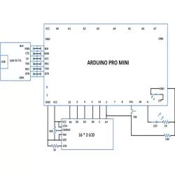
The Arduino board has several digital pins which can be configured as digital I/O pins and among them some can also be used as analog output pins. There are dedicated analog input pins in most of the Arduino boards. The Arduino pro-mini board has 8 analog input pins marked as A0, A1 up to A7. In this particular project the variable pin of a potentiometer is connected at the analog input pin A0.
The Arduino IDE provides functions to access analog input and analog output of the board. The code written for this project uses the built-in function provided by the Arduino IDE namely analogRead().
analogRead()
This function can read an analog value from an analog pin mentioned in its argument and can returns that value. Suppose if there is a variable ‘var’ into which the vlue of the analog pin A0 is need to be read into, one can use the analogRead() function as shown below;
var = analogRead(A0);
The above statement will enable the built-in ADC of the arduino’s microcontroller which then converts the analog value to its 10 bit digital equivalent and then stores in the variable ‘var’. The variable ‘var’ is expected to be of the type integer.
The Arduino IDE provides certain functions to generate a square wave at a particular frequency which is make use in this project. The functions are namely tone() and noTone() for start generating a square wave at a particular frequency and to stop the square wave respectively. The details of the functions are discussed in the following section;
tone()
The function tone is used to generate a square wave at the required, with a required frequency and also for a required period of time. The function basically has three parameters of which the first one indicates the pin number at which the wave can be generated, the second one is the frequency of the square wave and the third parameter is the time duration until which the wave should continue. The prototype of the function is given as follows;
tone ( pin_number, frequency, duration );
As an example to generate a square wave at a pin number 8, with a frequency 1KHz and for a duration 5 seconds the following statement can be used.
tone ( 8, 1000, 5000 );
When the wave is required to present at the particular pin until it is stopped by the noTone() function call the following statement can be used;
tone ( 8, 1000 );
noTone()
The function noTone can be used to stop the square wave exist in the pin number at which it has been initiated by the tone() function call. The function has a parameter which is the pin number where the wave has to be stopped. As an example the function can be used to stop the wave generated at the pin number 8 as shown in the following;
noTone(8);
[/nextpage][nextpage title=”Circuit Diagram” ]