Summary of RFID Interfacing with Arduino
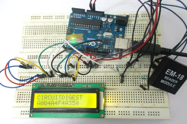
This tutorial explains how to design an RFID card reader system using Arduino UNO and an EM-18 RFID reader module. The system reads unique IDs from RFID cards, useful for access control in offices, schools, and shops. The project involves interfacing an RFID reader and a 16x2 LCD with Arduino, displaying card IDs on the LCD. The LCD is connected via specific Arduino pins, with power, control, and data lines detailed for proper operation. The system is cost-effective and applicable for attendance, theft prevention, and authorized entry systems.
Parts used in the RFID Card Reader System:
- ARDUINO UNO
- Power supply (5V)
- 100uF capacitor
- Buttons (two pieces)
- 1KΩ resistors (two pieces)
- EM-18 RFID reader module
- LED
- JHD_162ALCD (16x2 LCD)
- Arduino IDE (software)
In this tutorial we are going to design a system to read the ID of RFID cards. RFID stands for Radio Frequency Identification. Each card has a unique ID embedded in it. These systems have many applications, like in offices, shopping malls and in many other places where only the person with authorization card is allowed to enter in the room. RFID is used in shopping malls to stop a theft from happening, here the product will be tagged with RFID chip and when a person leaves a building with the RFID chip an alarm is raised automatically and so the theft is stopped. The RFID tag is designed as small as grain of sand. The RFID authentication systems are easy to design and are cheap in cost. Some schools and colleges nowadays use RFID as attendance register.
Components Required
Hardware: ARDUINO UNO, power supply (5v), 100uF capacitor , buttons (two pieces), 1KΩ resistor (two pieces), EM-18(RFID reader module), LED, JHD_162ALCD (16*2LCD).
Software: arduino IDE (Arduino nightly).
Circuit Diagram and Explanation
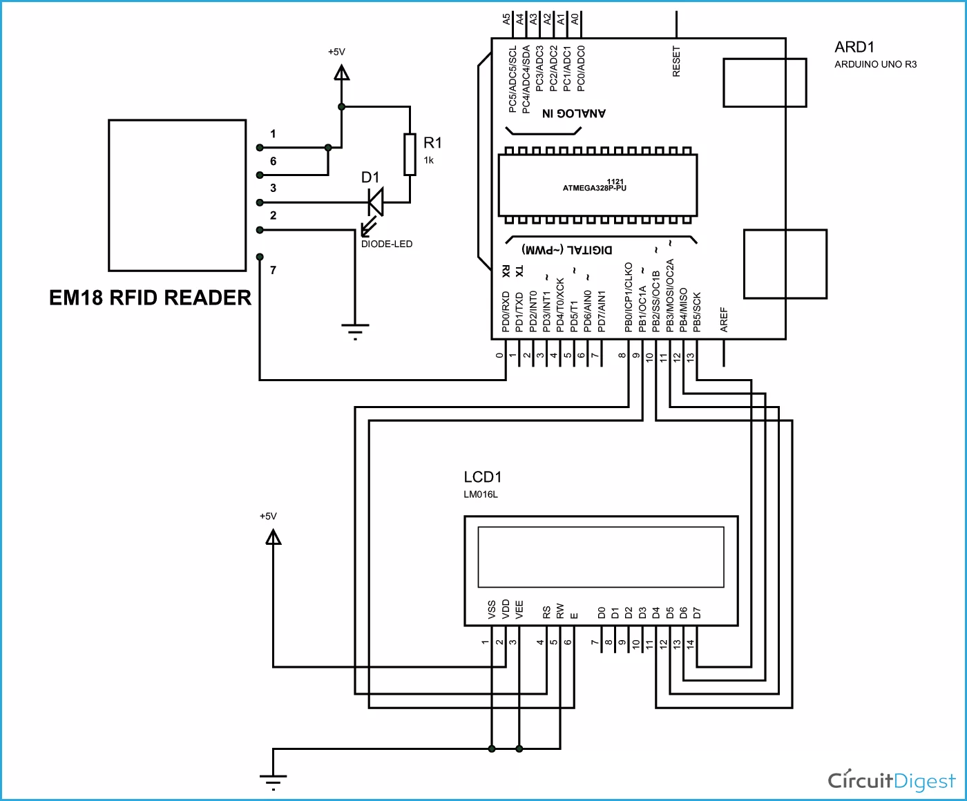
In 16×2 LCD there are 16 pins over all if there is a back light, if there is no back light there will be 14 pins. One can power or leave the back light pins. Now in the 14 pins there are 8 data pins (7-14 or D0-D7), 2 power supply pins (1&2 or VSS&VDD or GND&+5v), 3rd pin for contrast control (VEE-controls how thick the characters should be shown) and 3 control pins (RS&RW&E).
In the circuit, you can observe that I only took two control pins as his give the flexibility of better understanding. The contrast bit and READ/WRITE are not often used so they can be shorted to ground. This puts LCD in highest contrast and read mode. We just need to control ENABLE and RS pins to send characters and data accordingly.
The connections which are done for LCD are given below:
PIN1 or VSS to ground
PIN2 or VDD or VCC to +5v power
PIN3 or VEE to ground (gives maximum contrast best for a beginner)
PIN4 or RS (Register Selection) to PIN8 of ARDUINO UNO
PIN5 or RW (Read/Write) to ground (puts LCD in read mode eases the communication for user)
PIN6 or E (Enable) to PIN9 of ARDUINO UNO
PIN11 or D4 to PIN10 of ARDUINO UNO
PIN12 or D5 to PIN11 of ARDUINO UNO
PIN13 or D6 to PIN12 of ARDUINO UNO
PIN14 or D7 to PIN13 of ARDUINO UNO
Read More: RFID Interfacing with Arduino