Summary of Servo Motor Control using Arduino
This tutorial explains controlling a servo motor using an Arduino Uno. Servo motors provide precise shaft positioning suitable for low-speed, medium-torque applications such as robotics and flight controls. The motor has three wires: power (red), ground (black), and signal (yellow). Position control is achieved by sending a PWM signal to the signal pin, where the duty cycle determines the shaft angle (e.g., 1ms ON for 90°, 1.5ms ON for 12 o’clock). The Arduino generates this PWM signal, enabling accurate servo positioning. The circuit includes buttons for input and uses the Arduino IDE for programming.
Parts used in the Servo Motor Control Project:
- Arduino Uno
- Power supply (5V)
- 100µF capacitor
- Two push buttons
- Two 1KΩ resistors
- Servo motor
- Arduino IDE software
In this tutorial we are going to control a servo motor by ARDUINO UNO. Servo Motors are used where there is a need for accurate shaft movement or position. These are not proposed for high speed applications. These are proposed for low speed, medium torque and accurate position application. These motors are used in robotic arm machines, flight controls and control systems.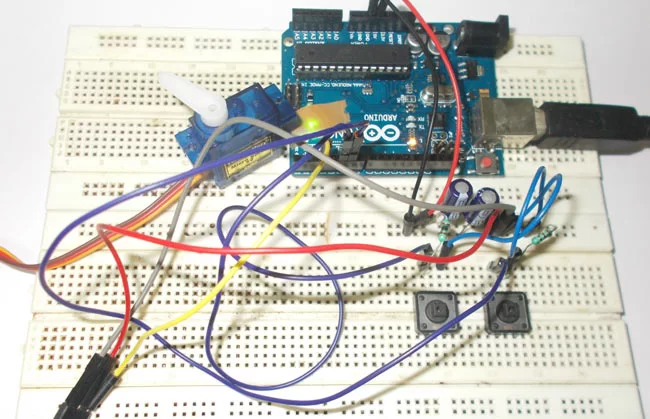
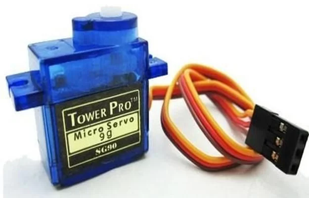
Servo motors are available at different shapes and sizes. A servo motor will have mainly there wires, one is for positive voltage another is for ground and last one is for position setting. The RED wire is connected to power, Black wire is connected to ground and YELLOW wire is connected to signal.
A servo motor is a combination of DC motor, position control system, gears. The position of the shaft of the DC motor is adjusted by the control electronics in the servo, based on the duty ratio of the PWM signal the SIGNAL pin.
Simply speaking the control electronics adjust shaft position by controlling DC motor. This data regarding position of shaft is sent through the SIGNAL pin. The position data to the control should be sent in the form of PWM signal through the Signal pin of servo motor.
The frequency of PWM (Pulse Width Modulated) signal can vary based on type of servo motor. The important thing here is the DUTY RATIO of the PWM signal. Based on this DUTY RATION the control electronics adjust the shaft.
As shown in figure below, for the shaft to be moved to 9o clock the TURN ON RATION must be 1/18.ie. 1ms of ON time and 17ms of OFF time in a 18ms signal.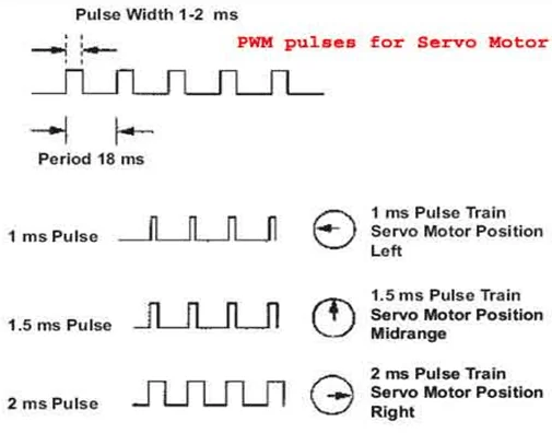
For the shaft to be moved to 12o clock the ON time of signal must be 1.5ms and OFF time should be 16.5ms. This ratio is decoded by control system in servo and it adjusts the position based on it. This PWM in here is generated by using ARDUINO UNO.
Circuit Components
Hardware: ARDUINO UNO, power supply (5v), 100uF capacitor , buttons (two pieces), 1KΩ resistor (two pieces), Servo motor (which needed to be tested).
Software: arduino IDE (Arduino nightly).
Read More: Servo Motor Control using Arduino