This ESP32 with Arduino IDE is an ESP32 Project that introduces how to program and use the ESP32 development board with the Arduino IDE. It covers the installation of board support packages, setting up the Arduino IDE, writing the first program, and uploading it to the ESP32. This beginner-friendly guide makes it easy to get started with ESP32 for IoT and embedded applications.
Project Type: ESP32 Project
- Step-by-step setup of ESP32 board support in Arduino IDE
- Writing and uploading the first sketch (example: Blink LED)
- Explains how to select the correct board and port in Arduino IDE
- Covers installation of USB-to-UART drivers for proper communication
- Demonstrates ESP32 as a versatile platform for IoT applications
| Component | Description |
|---|---|
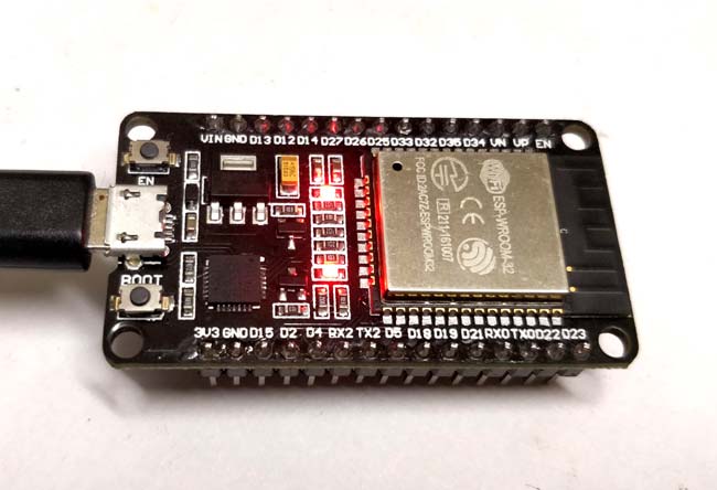
| ESP32 Dev Board | Main microcontroller for development |
| Micro USB Cable | For power supply and programming |
| LED + Resistor | External LED to test output (optional, built-in LED also) |
| Computer (PC/Laptop) | With Arduino IDE installed |
| Jumper Wires | For making optional LED connections |
| Breadboard | For prototyping (optional) |
- Arduino IDE Setup: Install Arduino IDE and configure it to support ESP32 boards by adding the required board manager URL.
- Driver Installation: Install the CP210x USB to UART driver or CH340 driver (depending on ESP32 board) to enable communication between the board and PC.
- Board Selection: In Arduino IDE, select the correct ESP32 board model and COM port.
- Programming: Write a simple sketch such as LED Blink. ESP32’s onboard LED or external LED connected to GPIO can be toggled on and off.
- Upload: Compile and upload the program to ESP32. Press and hold the BOOT button if required during uploading.
For the basic blink program, you can either use the onboard LED of the ESP32 or connect an external LED:
- Onboard LED: Usually connected to GPIO 2 (varies by board).
- External LED:
- Anode (+) → GPIO pin (e.g., GPIO 2) via current limiting resistor (220Ω).
- Cathode (–) → GND.

| Issue | Cause / Solution |
|---|---|
| Board not detected in IDE | Install correct USB-to-UART drivers, check cable and USB port |
| Upload fails (timeout) | Hold BOOT button during uploading, then release after “Connecting…” |
| Wrong board selected | Verify correct ESP32 board model is chosen in Arduino IDE board manager |
| LED not blinking | Check GPIO pin number in code, verify wiring and resistor connection |
| Serial Monitor not working | Ensure correct baud rate (default 115200) and correct COM port |
- Learning and experimenting with ESP32 programming
- Developing IoT prototypes with Wi-Fi and Bluetooth
- Home automation and sensor monitoring projects
- Low-power embedded systems
- Edge computing applications
- Advanced tutorials covering Wi-Fi connectivity
- Using Bluetooth/BLE features of ESP32
- Interfacing with sensors and actuators
- Building full IoT dashboards and cloud integration
- Exploring ESP-IDF as an alternative to Arduino IDE
| Parameter | Value |
|---|---|
| MCU | ESP32 (Tensilica Xtensa dual-core 32-bit) |
| Clock Frequency | Up to 240 MHz |
| RAM | 520 KB SRAM |
| Flash Memory | 4 MB (varies by board model) |
| Connectivity | Wi-Fi 802.11 b/g/n, Bluetooth v4.2 (BR/EDR + BLE) |
| GPIO | 34 programmable GPIO pins |
| Supply Voltage | 3.3V logic, powered via 5V USB |
| Programming Interface | Micro USB, UART-based |
If you found this helpful, please ⭐ star this repository and share it with others!
Built with 💡 by Circuit Digest
Making Electronics Simple
ESP32 Arduino IDE ESP32 Blink Program CP210x USB Driver IoT with ESP32
ESP32 GPIO programming ESP32 setup guide microcontroller programming
embedded systems ESP32 Wi-Fi Bluetooth