A man's hands are holding an assembly of 3D-printed parts. There is a white backplate, with a yellow circular piece running through the middle. The yellow piece is surrounded by metal rods. Another blue shaft runs through the left side of the assembly. A rougly-diamond shaped plate encompasses both of these shafts.

Designing A Simpler Cycloidal Drive

Cycloidal drives have an entrancing motion, as well as a few other advantages – high torque and efficiency, low backlash, and compactness among them. However, much as [Sergei Mishin] likes them, it can be difficult to 3D-print high-torque drives, and it’s sometimes inconvenient to have the input and output shafts in-line. When, therefore, he came across a video of an industrial three-ring reducing drive, which works on a similar principle, he naturally designed his own 3D-printable drive.

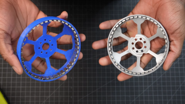
The main issue with 3D-printing a normal cycloidal drive is with the eccentrically-mounted cycloidal plate, since the pins which run through its holes need bearings to keep them from quickly wearing out the plastic plate at high torque. This puts some unfortunate constraints on the size of the drive. A three-ring drive also uses an eccentric drive shaft to cause cycloidal plates to oscillate around a set of pins, but the input and output shafts are offset so that the plates encompass both the pins and the eccentric driveshaft. This simplifies construction significantly, and also makes it possible to add more than one input or output shaft.

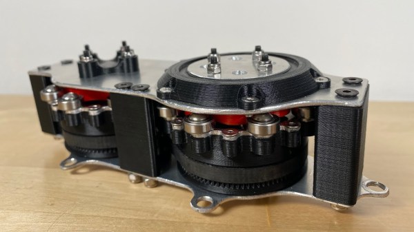
As the name indicates, these drives use three plates 120 degrees out of phase with each other; [Sergei] tried a design with only two plates 180 degrees out of phase, but since there was a point at which the plates could rotate just as easily in either direction, it jammed easily. Unlike standard cycloidal gears, these plates use epicycloidal rather than hypocycloidal profiles, since they move around the outside of the pins. [Sergei] helpfully wrote a Python script that can generate profiles, animate them, and export to DXF. The final performance of these drives will depend on their design parameters and printing material, but [Sergei] tested a 20:1 drive and reached a respectable 9.8 Newton-meters before it started skipping.

Even without this design’s advantages, it’s still possible to 3D-print a cycloidal drive, its cousin the harmonic drive, or even more exotic drive configurations. Continue reading “Designing A Simpler Cycloidal Drive”

Image

Compact Cycloidal Drive Lives Inside This Custom Brushless Motor

With the popularity of robot dogs, many people have gotten on the bandwagon and tried building DIY versions. Most of them end up attaching a gearbox to an off-the-shelf brushless motor and call it a day. Not everyone goes that way, though, which is why this internal cycloidal drive actuator caught our eye.

Taking design cues from the MIT Mini Cheetah, [Aaed Musa] approached his actuator from the inside out, literally. His 3D printed cycloidal gearbox is designed to fit inside the stator of a BLDC motor. And not just any BLDC motor, but one built mostly from scratch using a hand-wound — and unwound, and wound again — stator along with a rotor that started as a printed part but was eventually machined from steel. Apart from its fixed ring, the cycloidal drive was mostly 3D printed, with everything fitting nicely inside the stator.

The video below shows the design and assembly process as well as testing of the finished drive. It seems to do really well with speed and positional accuracy, and it delivers a substantial amount of torque. Maybe a little too much, though; testing it with a heavy weight on the end of an arm got the stator coils hot enough to warp the printed parts within. But no matter; this was only a prototype after all. [Aaed] says improvements are in the works, including replacing all the plastic parts with metal ones.

Need a little background on cycloidal drives? They’re pretty cool.

Continue reading “Compact Cycloidal Drive Lives Inside This Custom Brushless Motor”

Image

Differential Drive Doesn’t Quite Work As Expected

Placing two motors together in a shared drive is a simple enough task. By using something like a chain or a belt to couple them, or even placing them on the same shaft, the torque can be effectively doubled without too much hassle. But finding a way to keep the torque the same while adding the speeds of the motors, rather than the torques, is a little bit more complicated. [Levi Janssen] takes us through his prototype gearbox that attempts to do just that, although not everything works exactly as he predicts.

The prototype is based on the same principles as a differential, but reverses the direction of power flow. In something like a car, a single input from a driveshaft is sent to two output shafts that can vary in speed. In this differential drive, two input shafts at varying speeds drive a single output shaft that has a speed that is the sum of the two input speeds. Not only would this allow for higher output speeds than either of the two motors but in theory it could allow for arbitrarily fine speed control by spinning the two motors in opposite directions.

The first design uses two BLDC motors coupled to their own cycloidal drives. Each motor is placed in a housing which can rotate, and the housings are coupled to each other with a belt. This allows the secondary motor to spin the housing of the primary motor without impacting the actual speed that the primary motor is spinning. It’s all a lot to take in, but watching the video once (or twice) definitely helps to wrap one’s mind around it.

The tests of the drive didn’t go quite as planned when [Levi] got around to measuring the stall torque. It turns out that torque can’t be summed in the way he was expecting, although the drive is still able to increase the speed higher than either of the two motors. It still has some limited uses though as he notes in the video, but didn’t meet all of his expectations. It’s still an interesting build and great proof-of-concept otherwise though, and if you’re not clear on some of the design choices he made there are some other builds out there that take deep dives into cycloidal gearing or even a teardown of a standard automotive differential.

Continue reading “Differential Drive Doesn’t Quite Work As Expected”

Image

Robotic Arm Sports Industrial Design, 3D-Printed Cycloidal Gears

Image[Petar Crnjak]’s Faze4 is a open source robotic arm with 3D printable parts, inspired in part by the design of industrial robot arms. In particular, [Petar] aimed to hide wiring and cables inside the arm as much as possible, and the results look great! Just watch it move in the video below.

Cycloidal gearboxes have been showing up in robotic arm projects more and more, and Faze4 makes good use of them. Why cycloidal gears? They are readily 3D printed and offer low backlash, which makes them attractive for robotic applications. There’s no need to design cycloidal gears from scratch, either. [Petar] found this cycloidal gear generator in OnShape extremely useful when designing Faze4.

The project’s GitHub repository has all the design files, as well as some video demonstrations and a link to assembly documentation for anyone who would like to make their own. Watch Faze4 go through some test movements in the video embedded below.

Continue reading “Robotic Arm Sports Industrial Design, 3D-Printed Cycloidal Gears”

Image

Cycloid Drawing Machine Uses Sneaky Stepper Hack

Stepper motors are great for projects that require accurate control of motion. 3D printers, CNC machines and plotters are often built using these useful devices. [InventorArtist] built a stepper-based cycloid drawing machine, and made use of a nifty little hack along the way.

Image
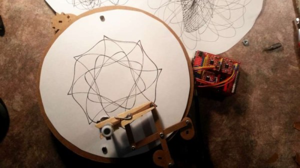
The machine uses a rotating turntable to spin a piece of drawing paper. A pen is then placed in a pantograph mechanism, controlled by another two stepper motors. The build uses the common 28BYJ-48 motor, which are a unipolar, 5-wire design. A common hack is to open these motors up and cut a trace in order to convert them to bipolar operation, netting more torque at the expense of being more complex to drive. [InventorArtist] worked in collaboration with [Doug Commons], who had the idea of instead simply drilling a hole through the case of the motor to cut the trace. This saves opening the motor, and makes the conversion a snap.

[InventorArtist] was able to create a machine capable of beautiful spirograph drawings, and develop a useful hack along the way. Reports are that a jig is in development to make the process foolproof for those keen to mod their own motors. We expect to see parts up on Thingiverse any day now. We’ve also covered the basic version of this hack before.

[Thanks to Darcy Whyte for the tip!]

Image

A Peek At The Mesmerizing Action Of A Cycloidal Drive

Cycloidal drives are fascinating pieces of hardware, and we’ve seen them showing up in part due to their suitability for 3D printing. The open source robot arm makers [Haddington Dynamics] are among those playing with a cycloidal drive concept, and tucked away in their August 2018 newsletter was a link they shared to a short but mesmerizing video of a prototype, which we’ve embedded below.

Image
A 10:1 Cycloidal Drive [Source: Wikipedia, image public domain]
A cycloidal drive has some similarities to both planetary gearing and strain-wave gears. In the image shown, the green shaft is the input and its rotation causes an eccentric motion in the yellow cycloidal disk. The cycloidal disk is geared to a stationary outer ring, represented in the animation by the outer ring of grey segments. Its motion is transferred to the purple output shaft via rollers or pins that interface to the holes in the disk. Like planetary gearing, the output shaft rotates in the opposite direction to the input shaft. Because the individual parts are well-suited to 3D printing, this opens the door to easily prototyping custom designs and gearing ratios.

[Haddington Dynamics] are the folks responsible for the open source robot arm Dexter (which will be competing in the Hackaday Prize finals this year), and their interest in a cycloidal drive design sounds extremely forward-thinking. Their prototype consists of 3D printed parts plus some added hardware, but the real magic is in the manufacturing concept of the design. The idea is for the whole assembly to be 3D printed, stopping the printer at five different times to insert hardware. With a robot working in tandem with the printer, coordinating the print pauses with automated insertion of the appropriate hardware, the result will be a finished transmission unit right off the print bed. It’s a lofty goal, and really interesting advancement for small-scale fabrication.

Continue reading “A Peek At The Mesmerizing Action Of A Cycloidal Drive”