 Morning.Star
 The Concept
Modern robotics hardware for the hobby market has been reduced to a series of modules, from servos to processors. The only things connecting these together are wire and chassis, and I've been experimenting with using easy to obtain materials to build those chassis. Polycarbonate and polystyrene, polyethylene, sheet aluminium etc were natural choices.
Mark's IO made me think again about the validity of cardboard as a working material, and we began a dialogue that culminated in this collaboration.
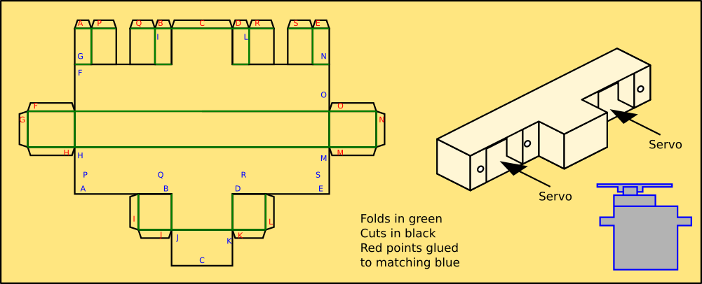
The idea is to use a single sheet of craft card and a printed template to create chassis units that connect the electromechanical building blocks together.
We have since iterated over a few changes to the design, incorporating better geometry to give the parts strength, room for cabling and better overall appearance.
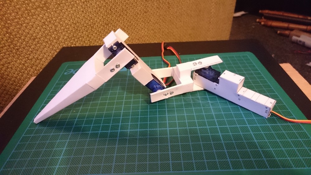
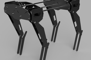
The first generation limb mounted on a spare thigh section so I can test the servos...
Mark Nesselhaus was able to replicate three of the pieces so far. If he can do it then anyone can. When using Super Glue please watch the fingers.
Once we had a working prototype chassis, the next job was to get the nervous system up and running.
Mark is now waiting for his 'brain' and 'muscles' to arrive via the postage system (fingers crossed) so he can duplicate the next stage himself... This is the real meat of the project, and forms the interactive part of the cardboard. I'm working on internalising the touch panels for the 2nd generation shell.
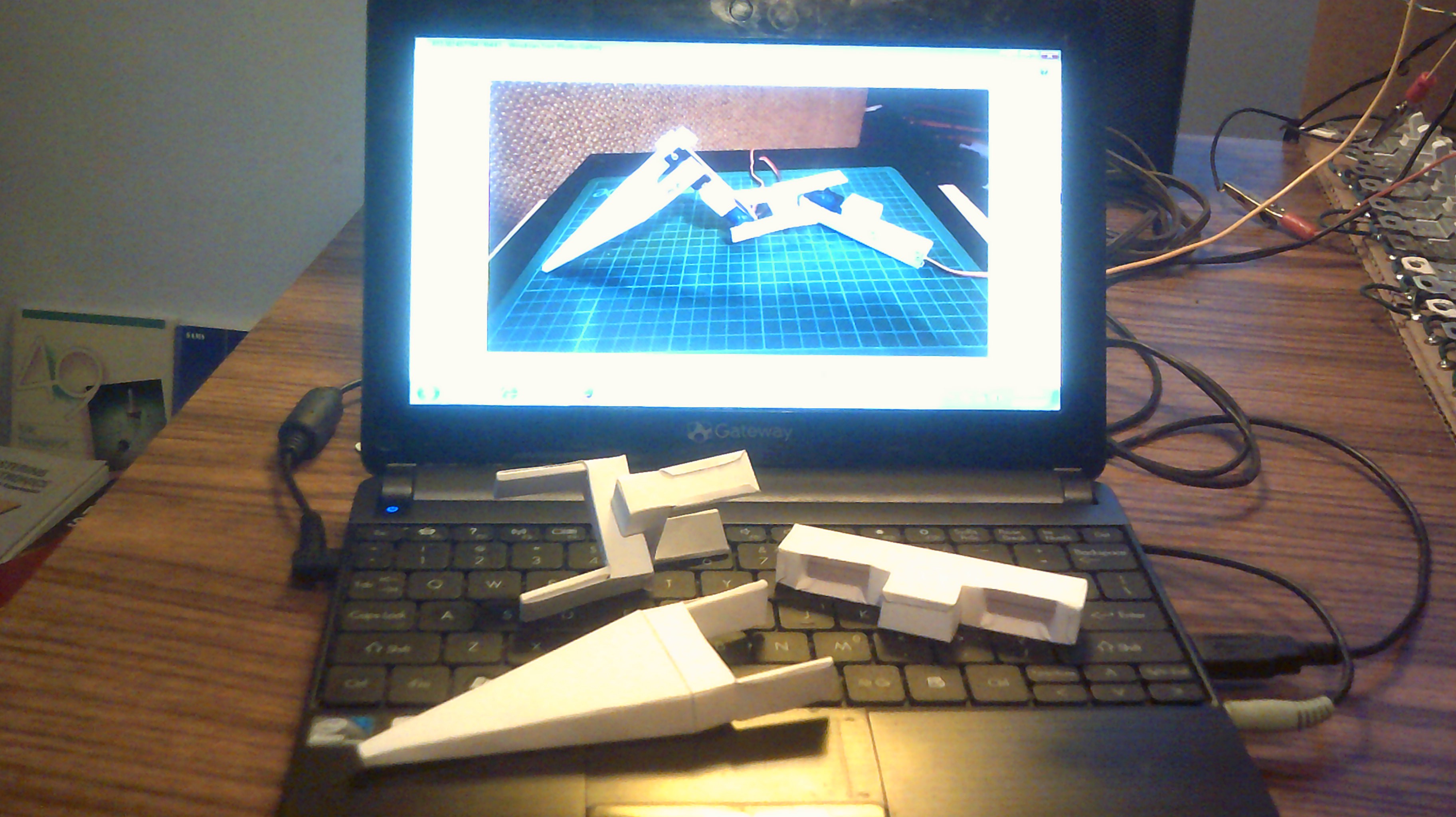
The nervous system in action on a first gen limb,attached to my PC. I'd managed to get it working how it was intended - it mimics the biological hallmark of withdrawing from a stimulus, and learning from the experience.
If you watch carefully, you can see that the servos are live and are holding the limb in position until I touch a surface, which it then withdraws from by a short distance. The system will record these motions and tag them to a hierarchical structure so you can 'program' the robot by touch alone. This only requires an MCU, but we are also using a RasPi with a camera and microphone to detect motion and shapes and respond to voice commands.
Testing the system on a Pi revealed the touch panels to be a lot more sensitive, and the cardboard literally came alive. I'm working on a way to integrate both these behaviours into the system.
Origaime - The next generation
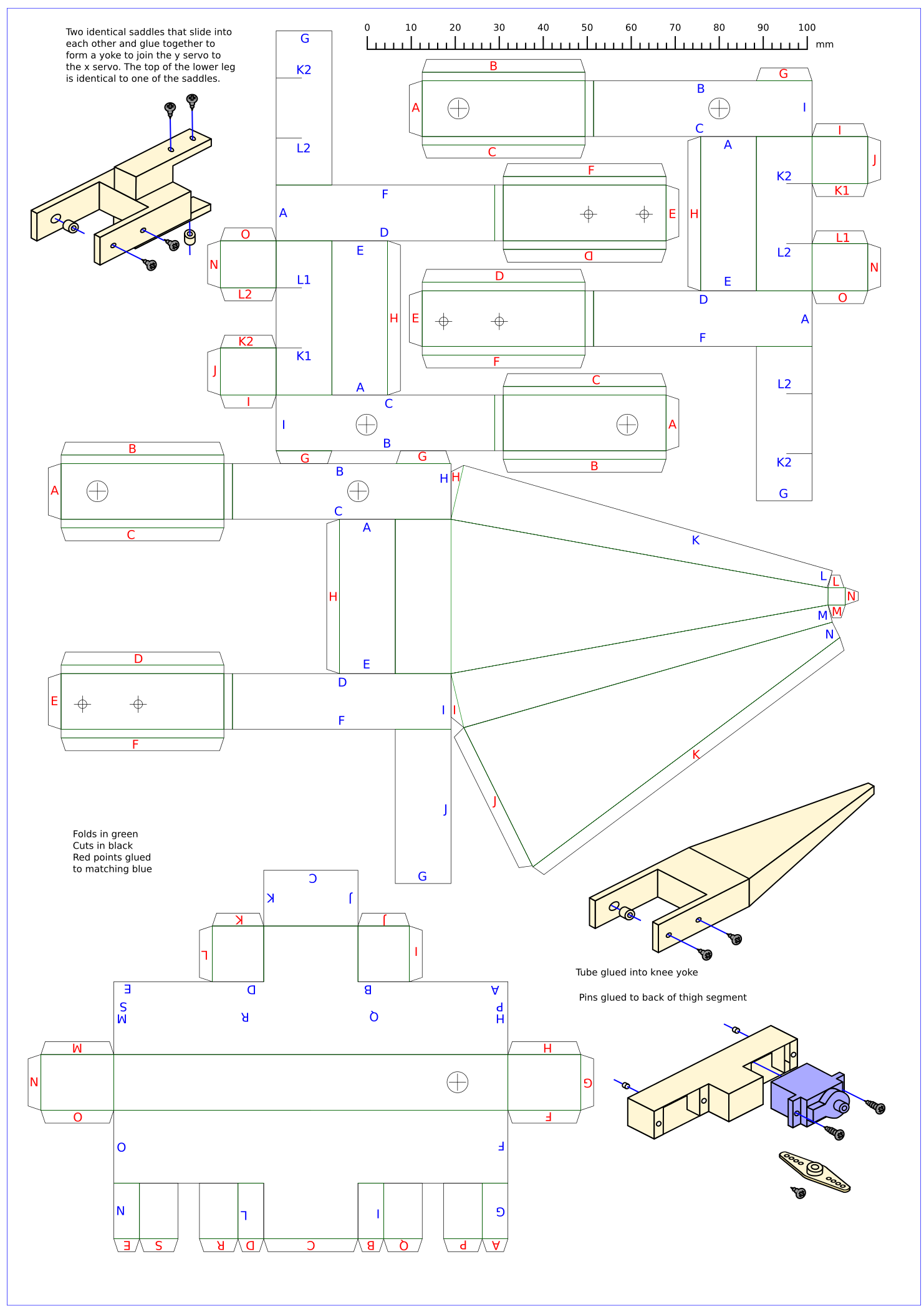
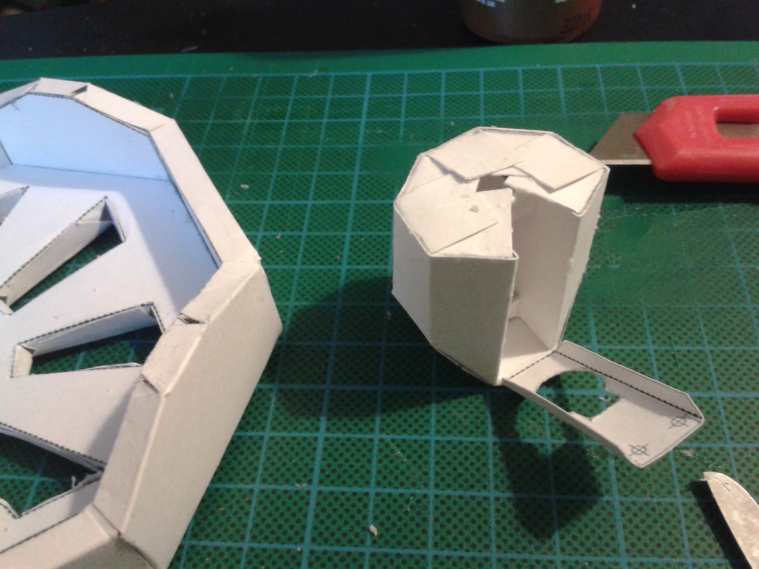
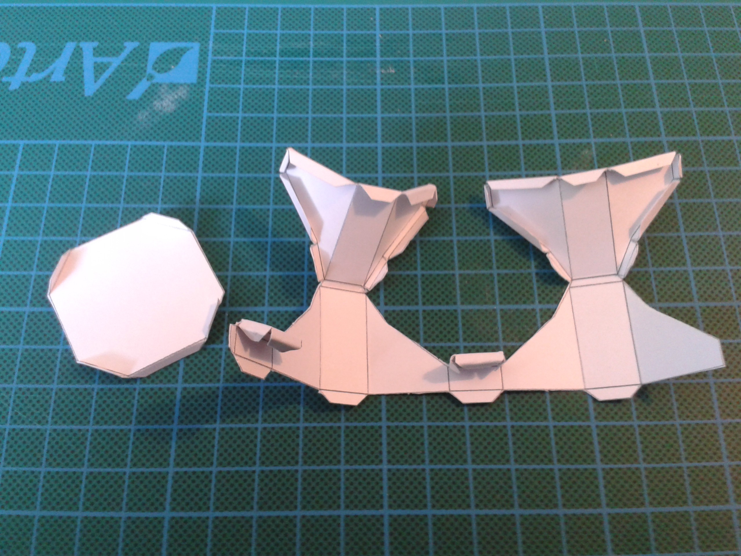
The new parts build in exactly the same way as the first set, they fold up from a single piece of cardboard to make a modular piece for the robot. Mark calls this Origaime, after the original robot that inspired everything and the art of folding. :-)
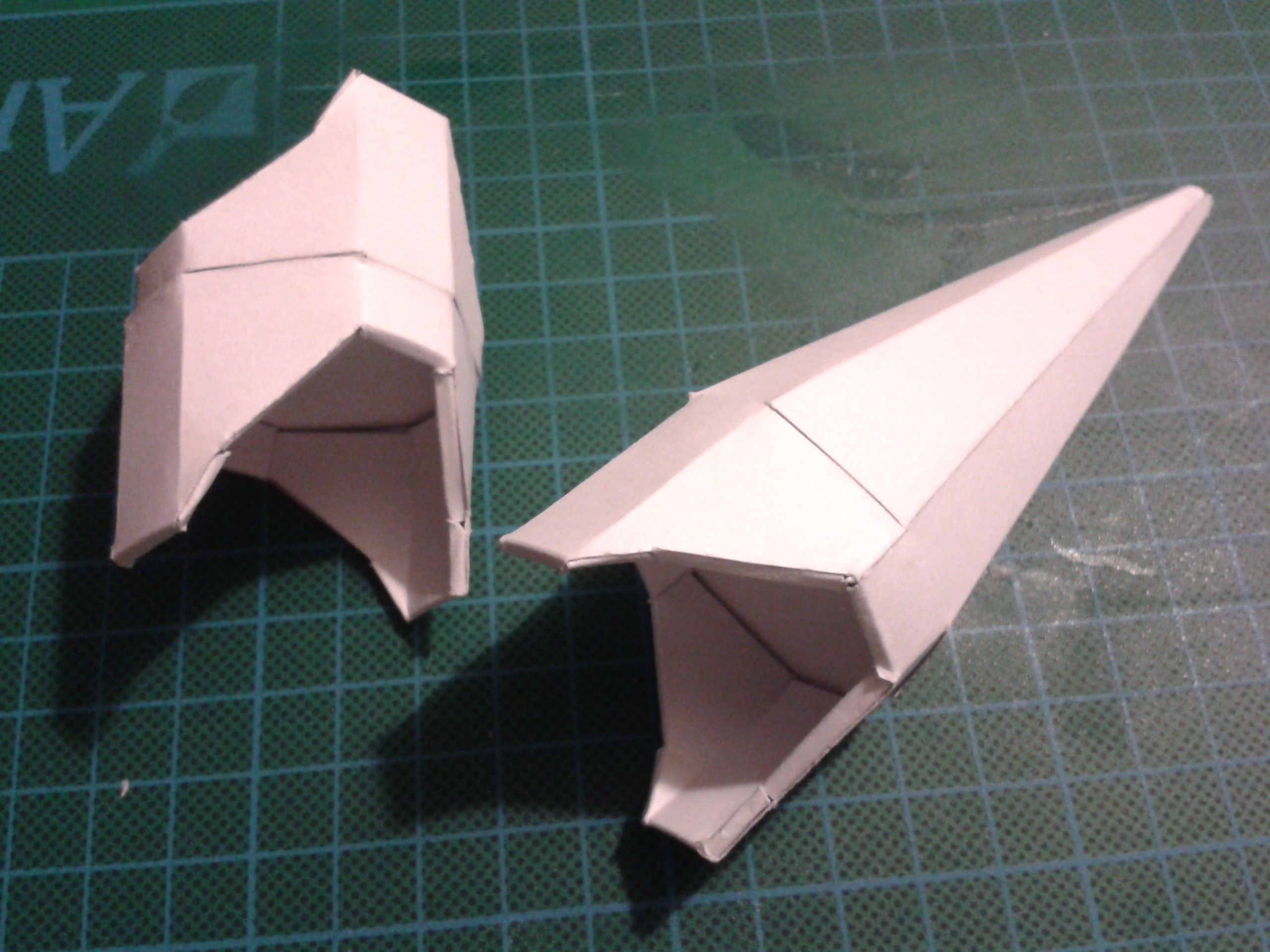
Both these pieces were accomplished using the redesigned saddle that fits over the servo actuator and a stud fitted opposite it to make a live hinge.
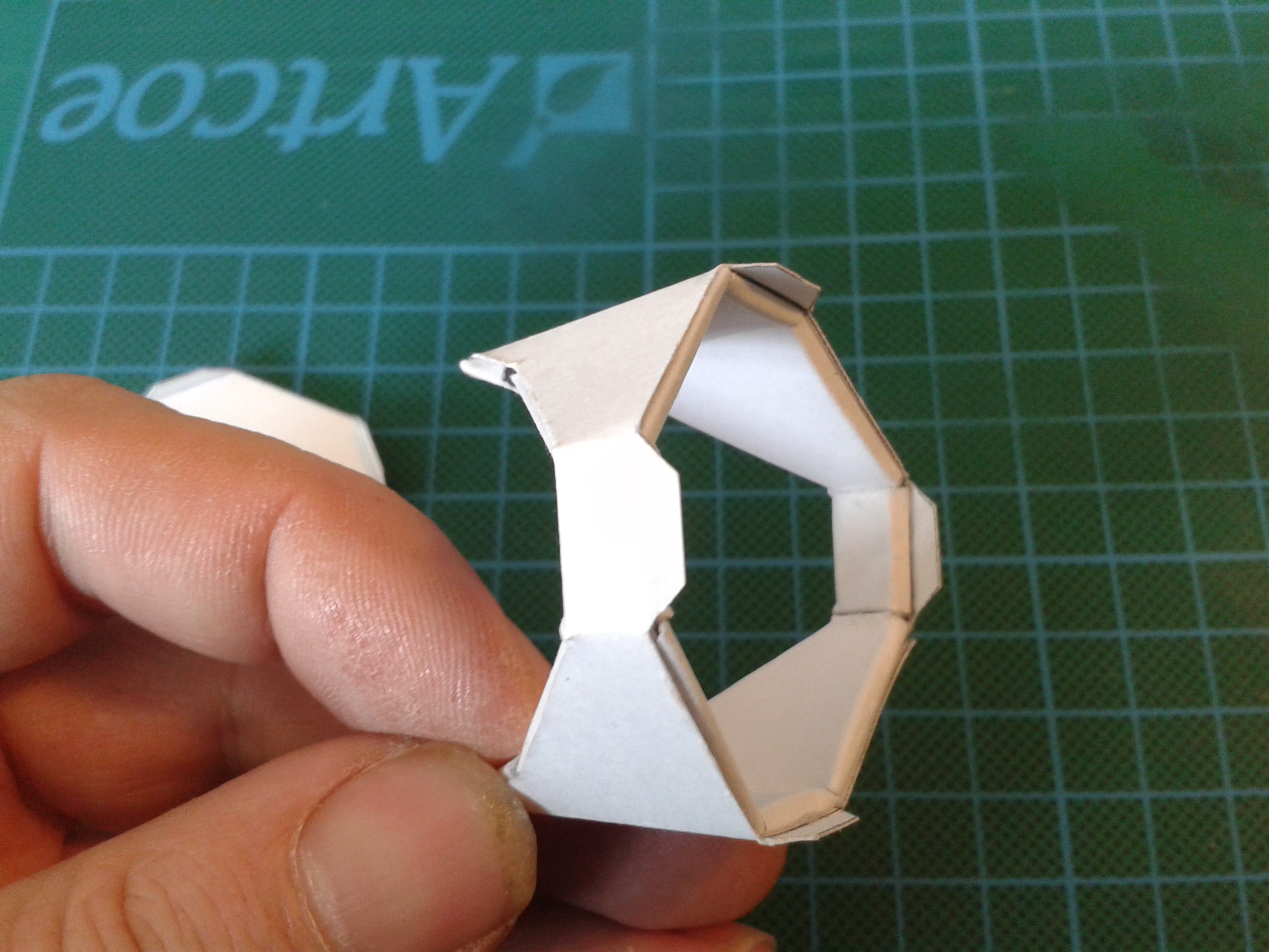
The section that joins these together to make active limbs as also made from one piece. This part carries the servos and the stud for the saddle to rotate over. Eventually there will be a range of part styles that can make any articulation you like, not just basic limbs.

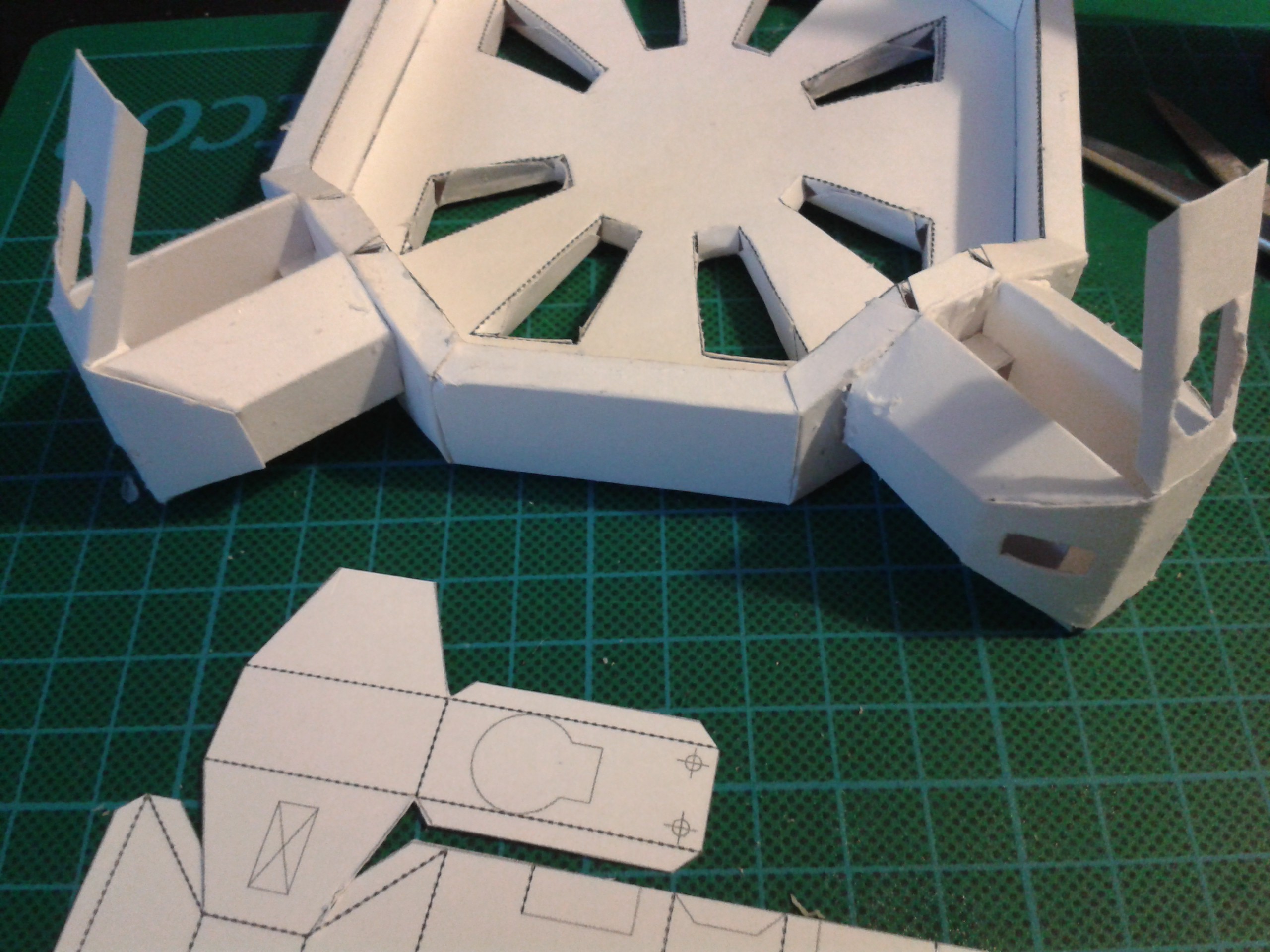
This has been reworked to include the servo bearers out of the chassis instead of separate pieces. This better fits the Way of Origaime...
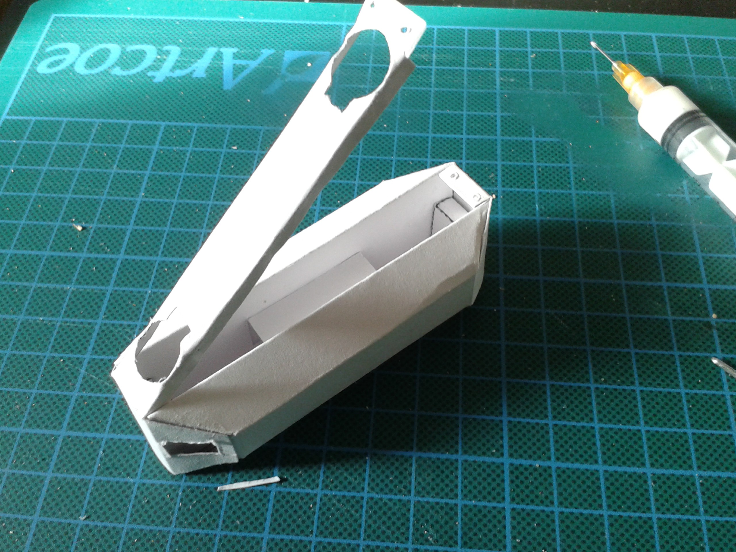
As I said, these parts are modular. Here's the other end being prototyped onto the shell at the body end. I hope hip replacements get this easy in the future.
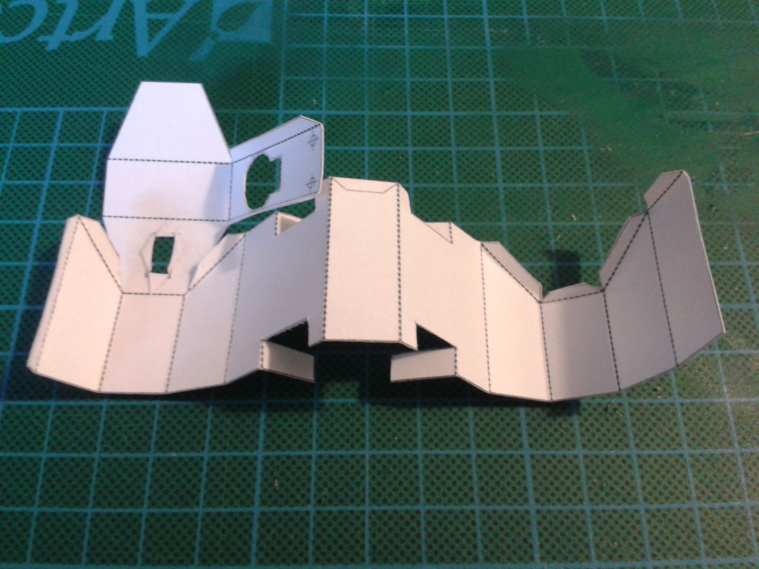
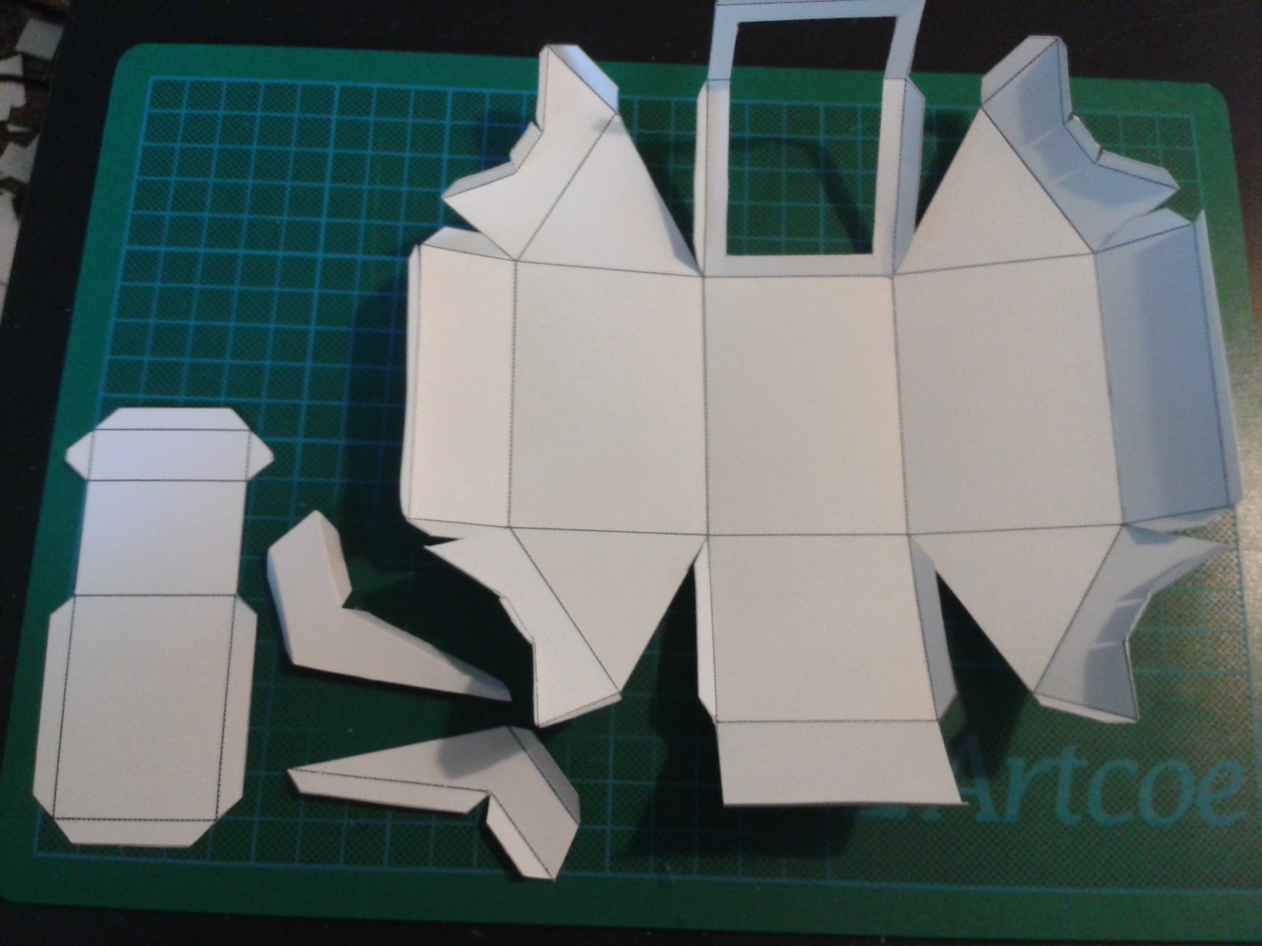
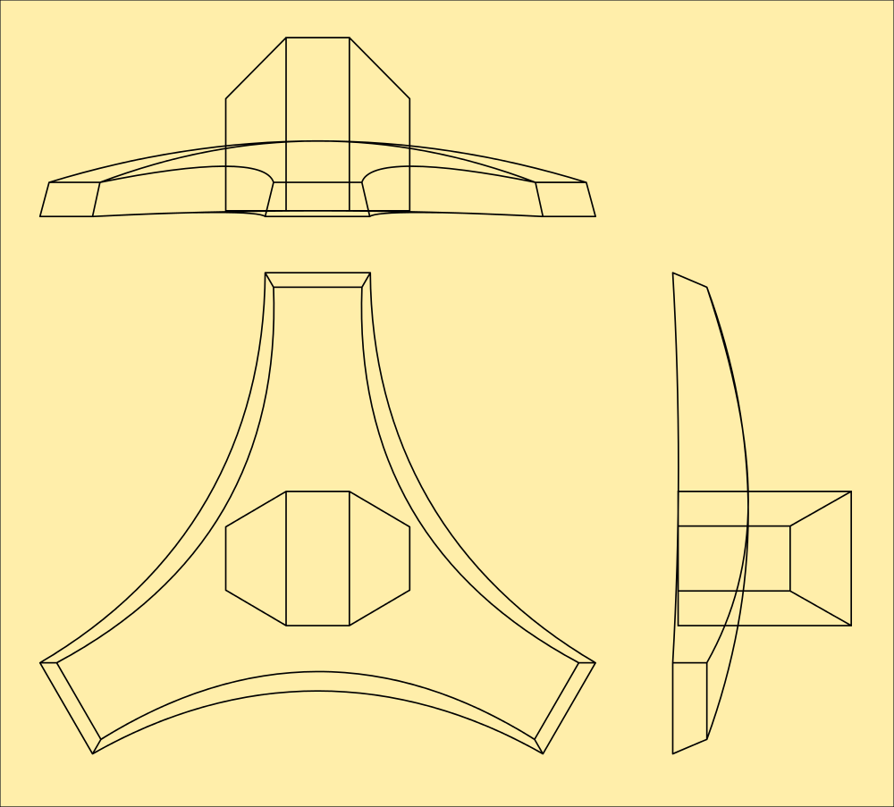
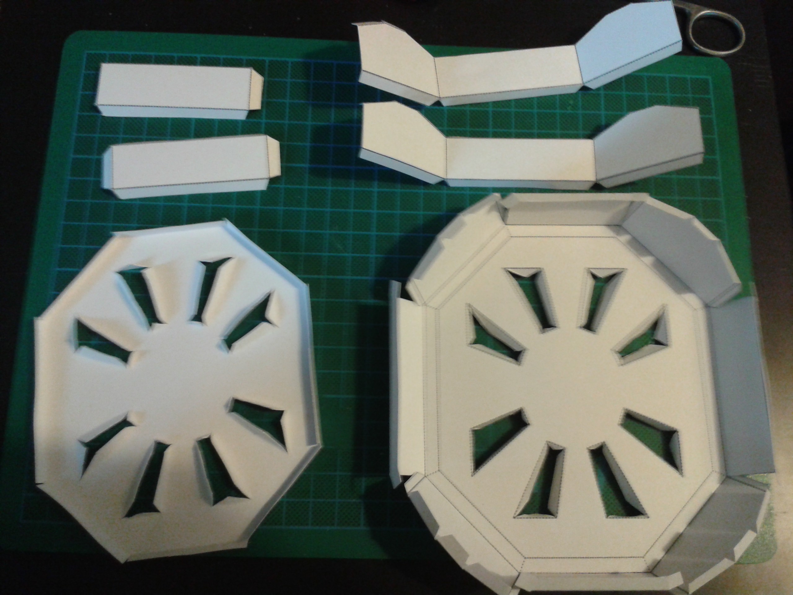
And the shell itself of course. This features a customisable panel in the bottom which is used to provide ventilation for the electronics and also structural integrity. This part has the greatest amount of stress to deal with and needs to be solid. I chose a pattern I knew would do this, but then I realised this could be used to aesthetic effect, and I'm going over a few designs for graphics in here. Watch this space... ;-)

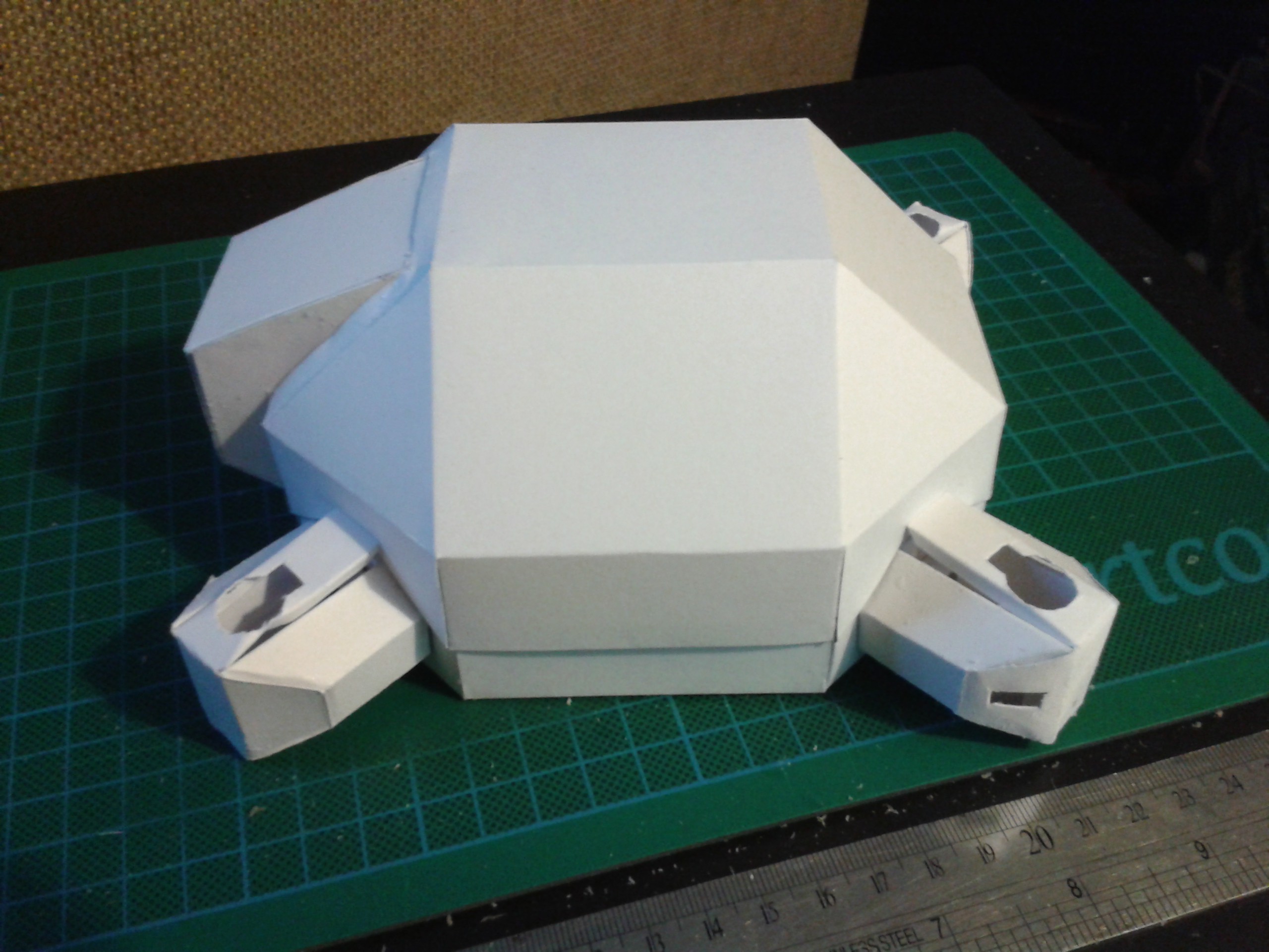
Here's a picture of what it looks like after a couple of strong beers. Nobody's perfect. ;-)
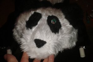
It needs a lid still, that is for now a simple octohedral dome with a port for the camera. I'm still working on this too.
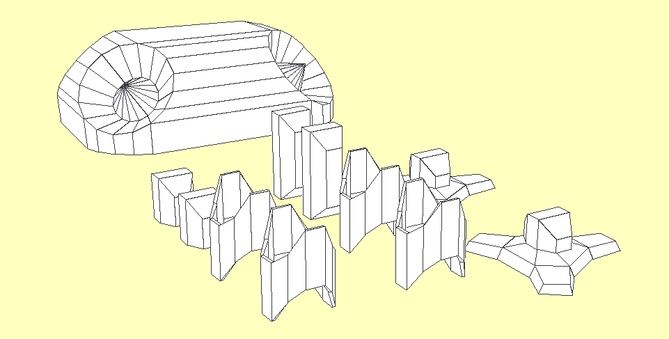
All together...
Read more »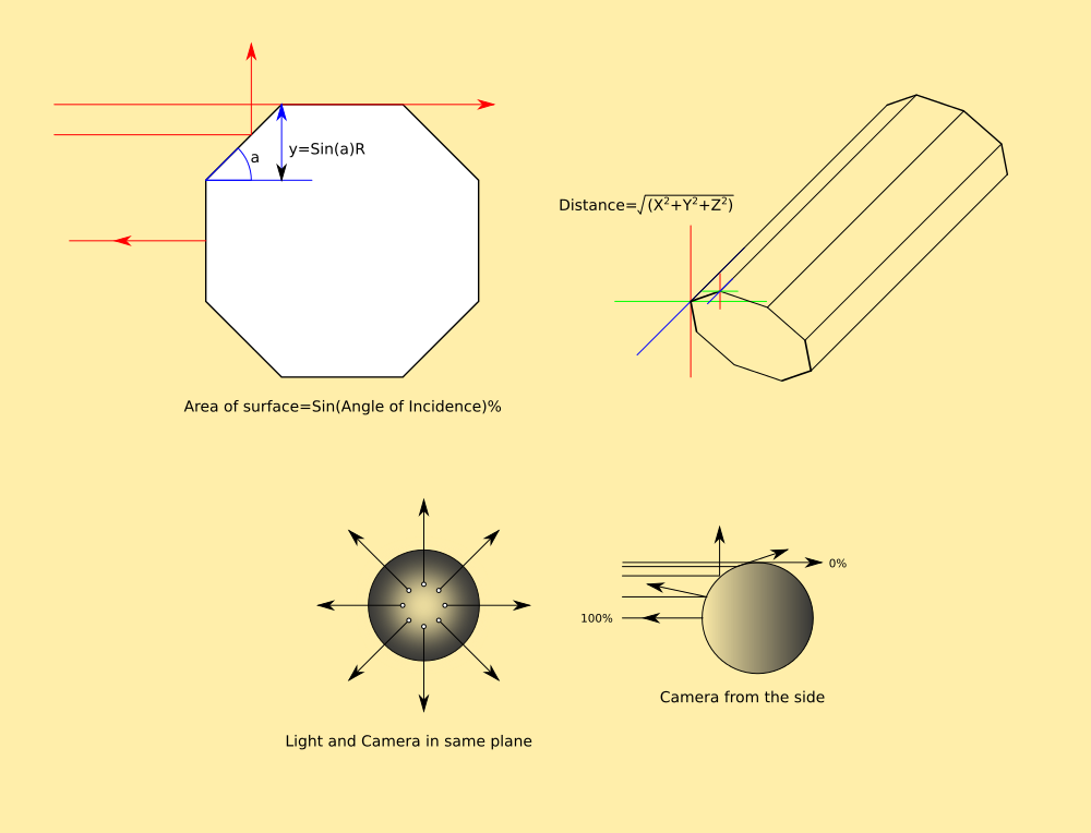

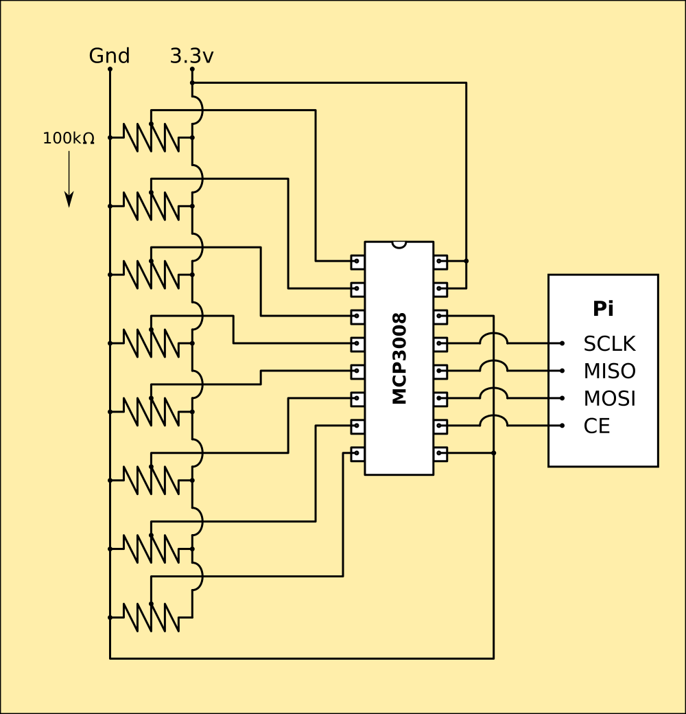 Pretty much plug the chip into the Pi's GPIOs and cable it to the sensors and thats done. Pi has software SPI so I can configure the GPIOs in code. I've ordered one, but it wont arrive until the weekend.
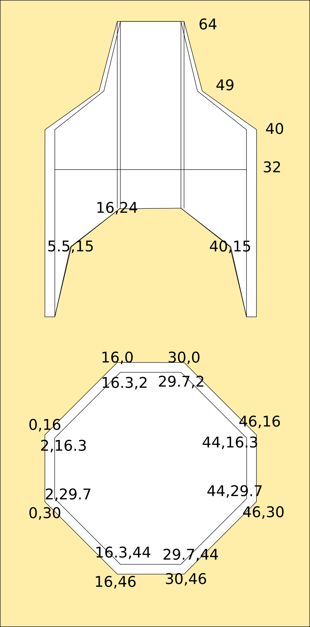
 But what about horrible shapes like these (and they will be really easy to create by exploring...)
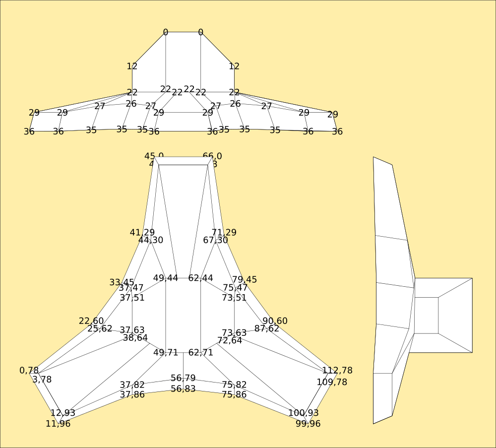
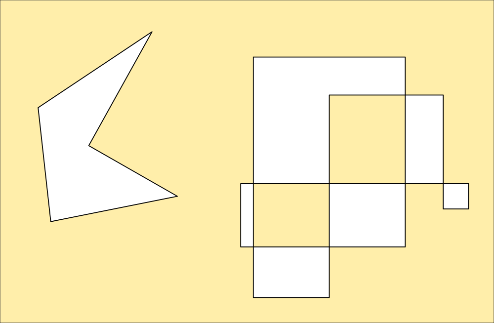 That second one is particularly nasty. Inkscape has a special routine to handle it in one of several ways depending on how you want it filled. This is default; areas that cross areas already used by the shape are considered outside, unless they are crossed again by a subsequent area. This is how the code snippet interprets a polygon like that, and its useful for making areas from paths for example.
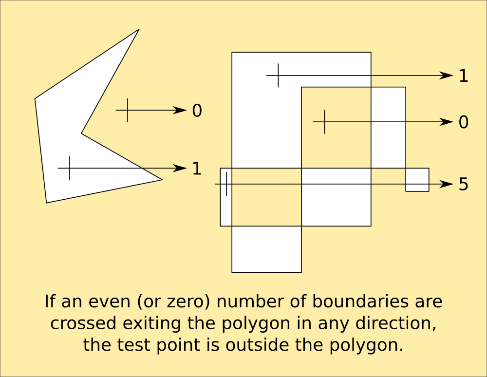 This is of particular use for sequential-turn mapping of an area, because it identifies the areas enclosed by the path that need exploring, as turns are generated by obstacles that might not be boundaries.
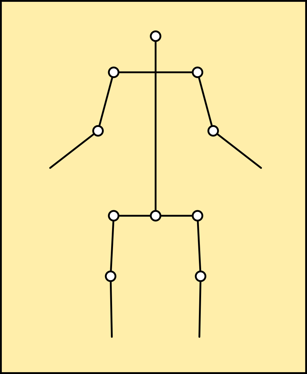
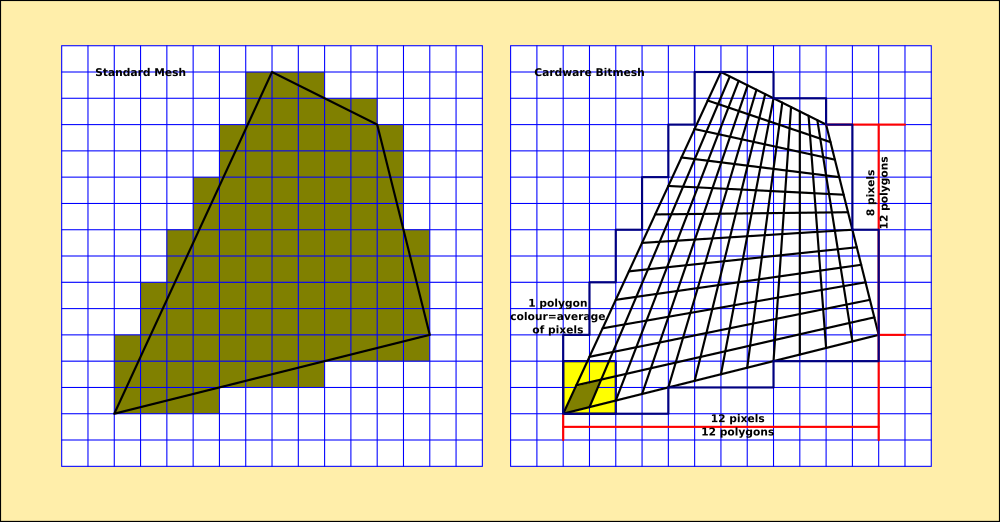
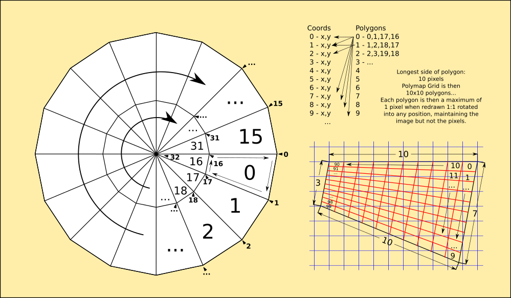
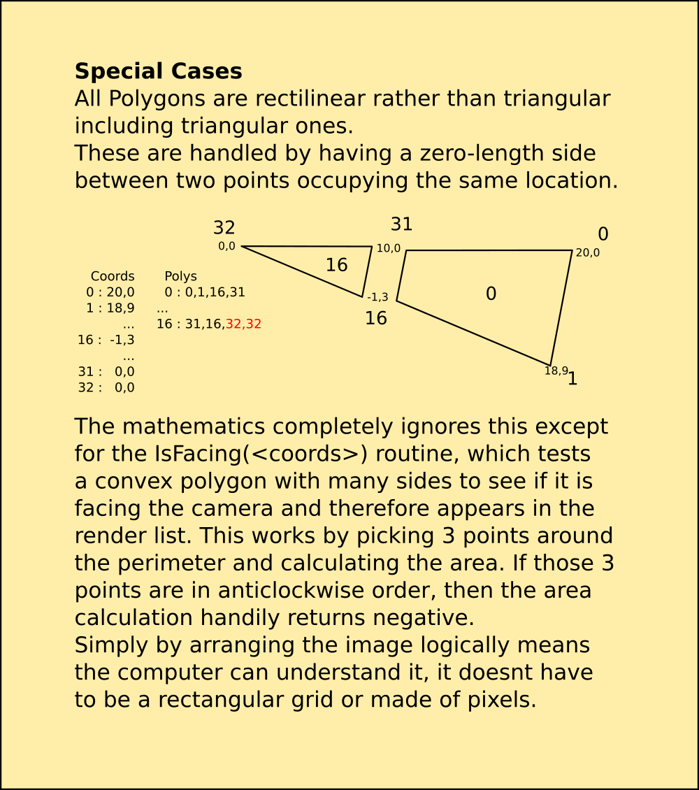
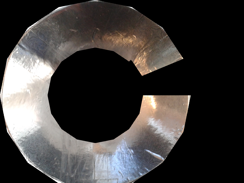
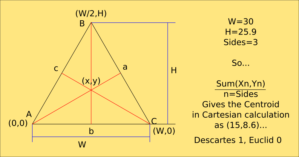
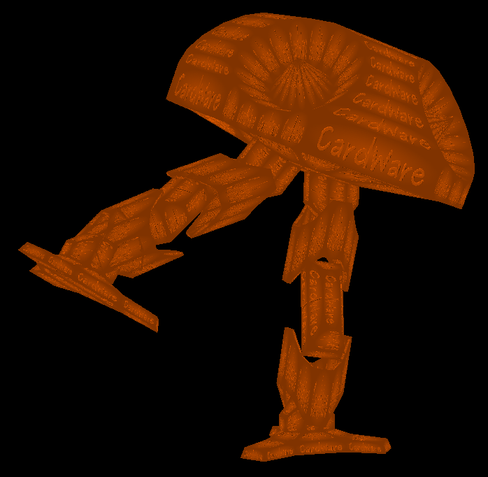
 Most of this code will be rewritten in C++ so I can draw those polygons with my own routines and handle the depth on a per-pixel level. This also means I can wrap a photograph of the real one around it. Python is way too slow for this without a library, and PyGame's polygon routines would still be terrible if they understood 3D coordinates. ;-)
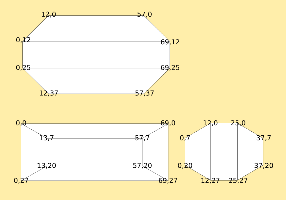
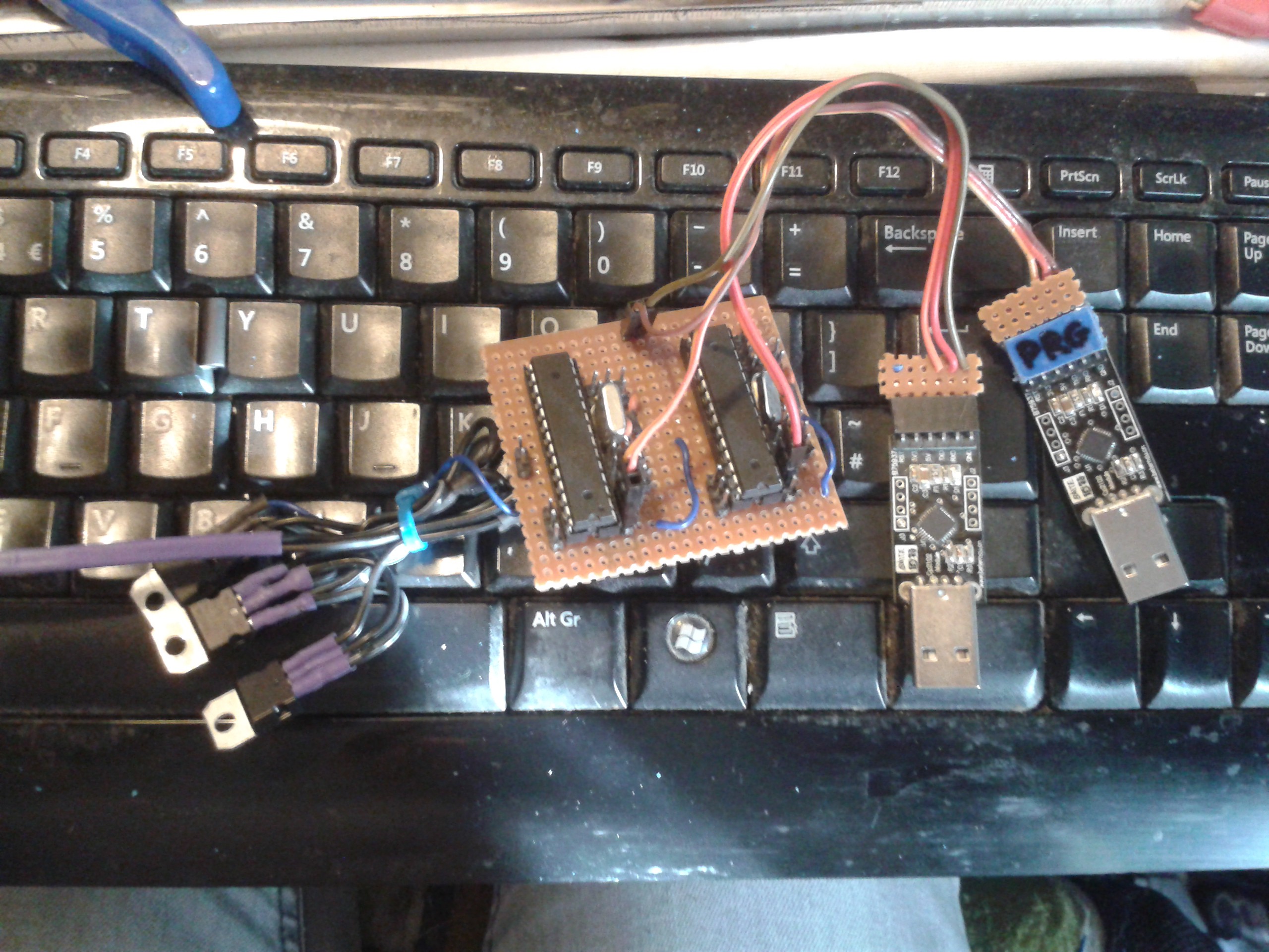
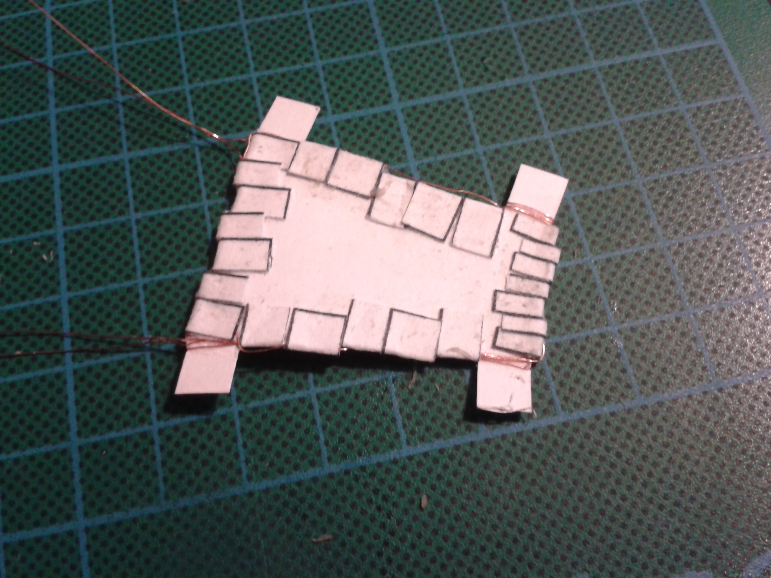
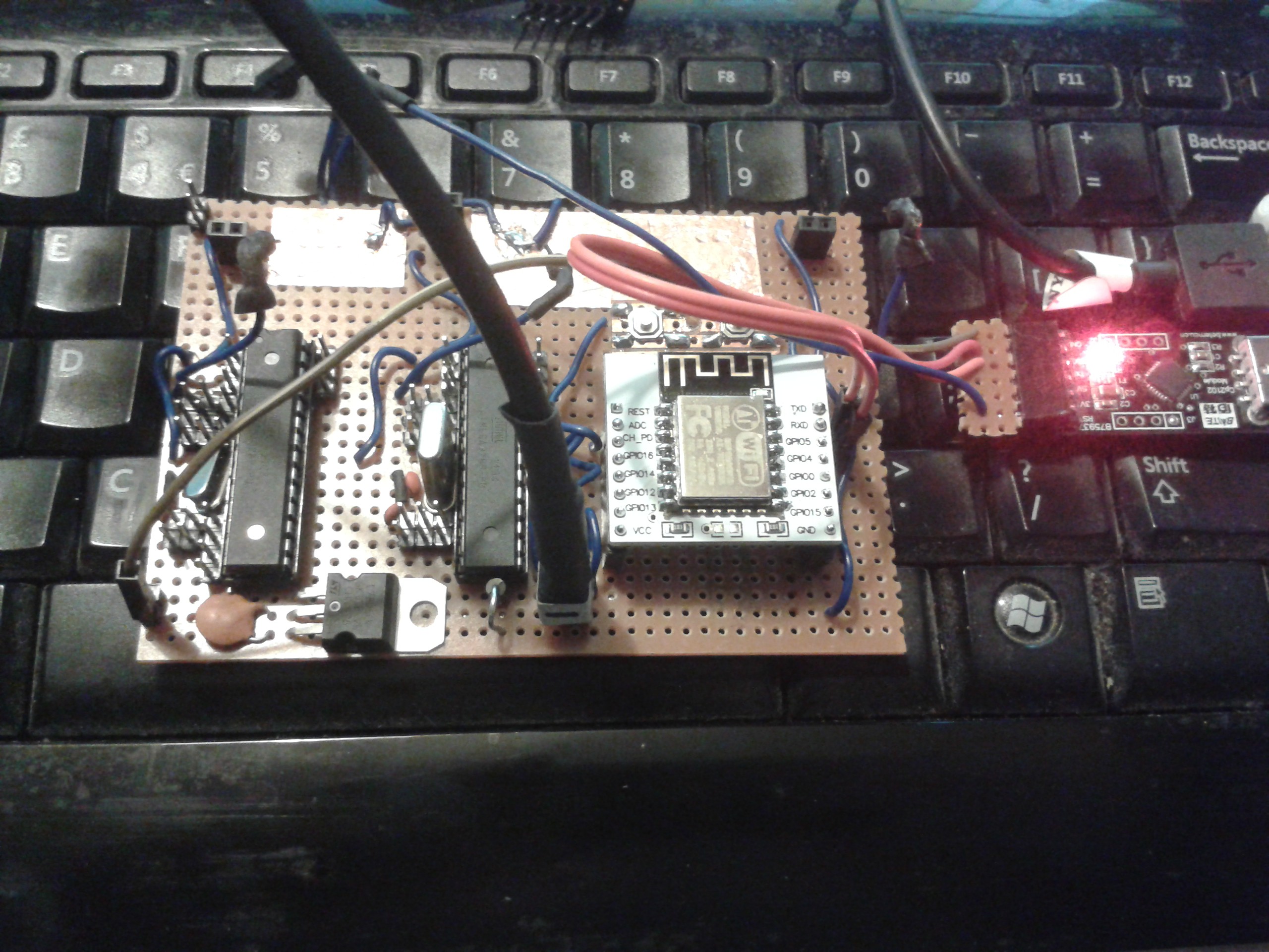 Using the multiprocessor serial networking. The TX of each is on a flylead that plugs into the RX of the next, and its broken out on the top left corner so I can connect the TX and RX of the UART.
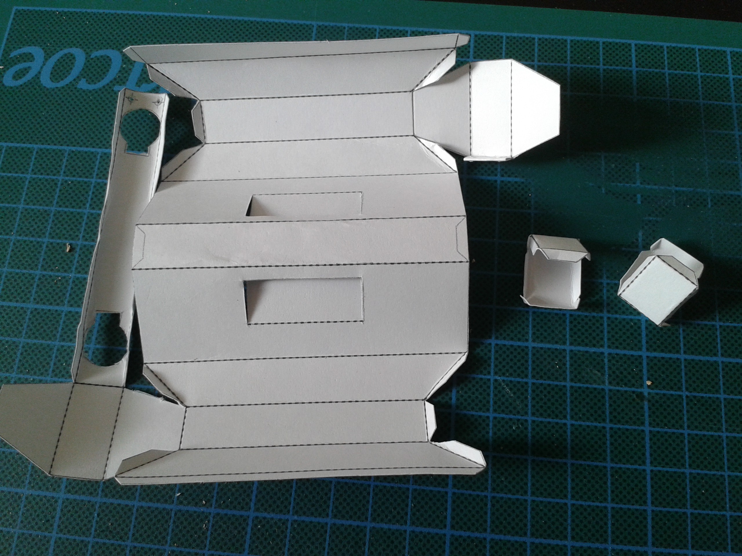


 Ben Nortier
 freeflightlab
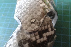
Cardware officially welcomes another collaborator.
Irony begs me to point out that I now have two cardboard Generals, Mark One and Mark Two.
XD