In this tutorial, you’ll learn how the 74HC595 shift register works, how to wire it up to an Arduino Uno, and how to control multiple outputs (like LEDs) using example code.
When working on Arduino projects, sometimes you need to control more output devices — like LEDs, relays, or sensors — than the available GPIO pins allow. So, how do you expand the I/O abilities of an Arduino Uno? The answer lies in using a shift register, and one of the most popular options is the 74HC595.
The 74HC595 is a Serial-In Parallel-Out (SIPO) shift register that lets you control 8 outputs using just 3 Arduino pins. You can also daisy-chain multiple 74HC595 ICs to expand outputs further.
What is a Shift Register and Why Use It?
A shift register is a digital storage device that allows data to be shifted in and out serially and read or written in parallel. It helps expand I/O capabilities of microcontrollers like the Arduino.
There are two types:
- SIPO (Serial-In Parallel-Out) — used to expand outputs (e.g., 74HC595)
- PISO (Parallel-In Serial-Out) — used to expand inputs (e.g., 74HC165)
Imagine controlling a full 8×8 LED matrix, which has 64 individual LEDs. That would require 64 output pins! But by using two 74HC595 ICs — one for rows and one for columns — you can control the entire matrix with just 6 Arduino pins.
Features of the 74HC595
- 8-bit serial-in, parallel-out
- D-type latch storage register
- 3-state outputs (HIGH, LOW, High-Impedance)
- Daisy-chain capability
- Operates at 2V to 6V, compatible with 5V logic
- Low power consumption
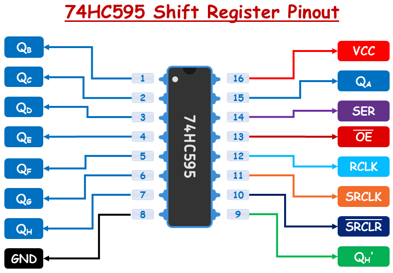
74HC595 Shift Register Pinout
Output Pins (QA to QH or Q0 to Q7): These are the eight output pins that represent the stored data bits. Each pin outputs one bit from the internal storage register.
Serial Data Input (SER or DS): This is where the data is fed into the shift register one bit at a time (starting from the least significant bit).
Shift Register Clock (SRCLK): A rising edge (LOW to HIGH transition) on this pin shifts the data into the shift register. Every pulse moves bits by one position.
Storage Register Clock / Latch (RCLK): When this pin receives a rising edge, the data in the shift register is transferred to the output (storage) register. The outputs (QA to QH) update only when this clock is triggered.
Cascade Output (QH’): Outputs the last bit (QH) of the shift register. Used to connect multiple 74HC595 ICs in series for expanding outputs (daisy-chaining).
Output Enable (OE): This is an active LOW pin. When it is LOW, outputs are enabled. When it is HIGH, outputs go into high-impedance (disconnected) mode. You can use PWM on this pin to control LED brightness connected to outputs.
Shift Register Clear (SRCLR): This is an active LOW pin. When LOW it clears all bits in the shift register (sets them to 0). Typically connected to Vcc if not used.
Power Supply (VCC): Connects to 5V power supply.
Ground (GND): Connects to ground (0V).
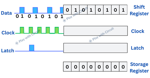
How the 74HC595 Shift Register Works?
The 74HC595 operates using two internal registers:
- Shift Register — Temporarily holds data as it’s being received.
- Storage Register (Latch) — Holds the final data and controls the output pins (QA to QH).
Loading Data into the Shift Register
- Data is input bit by bit through the Serial Data (SER) pin.
- Every time the Shift Register Clock (SRCLK) receives a rising edge (from LOW to HIGH), all existing bits in the shift register shift one position to the left (from LSB to MSB).
- The least significant bit (LSB) of the register is updated with the current logic level at the SER pin.
- This process continues until all 8 bits are loaded into the shift register.
Transferring Data to Outputs
- Once all 8 bits are loaded, a pulse is sent to the Latch Pin (RCLK).
- This copies the data from the shift register to the storage register.
- The outputs QA to QH are updated based on the values in the storage register.
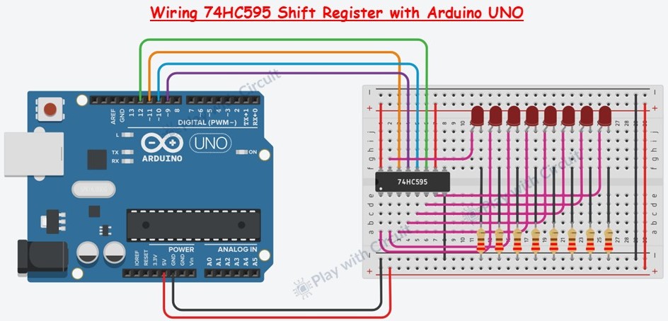
Wiring the 74HC595 to Arduino
We will use the shift register to control 8 red LEDs connected to output pins QA to QH.
Place the 74HC595 IC on your breadboard, with each side of pins on separate breadboard rails.
Identify Pin 1 — it’s just to the left of the small notch or dot on the IC.
Connect Power Pins:
- Pin 16 (VCC) → 5V on Arduino
- Pin 10 (SRCLR) → 5V on Arduino (disables clearing)
- Pin 8 (GND) → GND on Arduino
Enable Output:
- Pin 13 (OE) → Arduino Pin 9 (PWM-enabled for brightness control)
Connect Control Pins:
- Pin 11 (SRCLK) → Arduino Pin 12 (Shift Clock)
- Pin 12 (RCLK) → Arduino Pin 10 (Latch Clock)
- Pin 14 (SER) → Arduino Pin 11 (Serial Data Input)
Connect Anode of LEDs to Output Pins (QA to QH):
Pins 15 (QA), 1 (QB), 2 (QC), 3 (QD), 4 (QE), 5 (QF), 6 (QG), 7 (QH)
- Connect a 220Ω resistor in series with each LED.
- LED anodes go to the shift register outputs; cathodes go to GND.
Arduino Code
/*
Code to interface 74HC595 SIPO shift register using Arduino UNO
by www.playwithcircuit.com
*/
//Pin connected to SH_CP of 74HC595
int clockPin = 12;
//Pin connected to DS of 74HC595
int dataPin = 11;
//Pin connected to ST_CP of 74HC595
int latchPin = 10;
//Pin connected to OE of 74HC595
int brightnessPin = 9;
//Brightness control variable
int PWM_Value = 0;
void setup() {
  //set pins to output so you can control the shift register  and initially they should be HIGH
  pinMode(latchPin, OUTPUT);
  pinMode(clockPin, OUTPUT);
  pinMode(dataPin, OUTPUT);
  pinMode(brightnessPin, OUTPUT);
  digitalWrite(latchPin, HIGH);
  digitalWrite(clockPin, HIGH);
  digitalWrite(dataPin, HIGH);
  analogWrite(brightnessPin, 255);
}
void loop() {
  int led_byte = 0x00;
  //  turn ON all LEDs one by one
  for (int i = 0; i < 8; i++) {
    // adjust the brightness of LEDs
    PWM_Value = (255 - (115 + (20*i)));
    analogWrite(brightnessPin, PWM_Value);
    led_byte |= (0x01 << i);
    // take the latchPin low
    digitalWrite(latchPin, LOW);
    // shift out the bits:
    shiftOut(dataPin, clockPin, MSBFIRST, led_byte);
    //take the latch pin high so the LEDs will light up:
    digitalWrite(latchPin, HIGH);
    // pause before next value:
    delay(100);
  }
  //  turn OFF all LEDs one by one
  for (int i = 0; i < 8; i++) {
    led_byte &= ~(0x01 << i);
    // make the latchPin low
    digitalWrite(latchPin, LOW);
    // shift out the bits:
    shiftOut(dataPin, clockPin, MSBFIRST, led_byte);
    //make the latch pin high so the LEDs will light up:
    digitalWrite(latchPin, HIGH);
    // pause before next value
    delay(100);
  }
}