Instrumentation for force, torque, strain, temperature, angular speed and position, and acceleration measurements.
Michigan Scientific Corporation
Excellence in Engineering For Over 60 Years
Instrumentation for force, torque, strain, temperature, angular speed and position, and acceleration measurements.
The Design, Manufacture, and Calibration for Wheel Force Transducers, Wheel Torque Transducers, and Load Cells is certified to the ISO9001:2015 standard. Mass, Force, and Weighing Devices and Mechanical Calibration is accredited to ISO/IEC 17025:2017 standards.

The CBT-MICRO is a wireless, battery-powered signal transmitter for strain gauges. It easily mounts to shafts with a minimum diameter of 25 mm or larger and is packaged in a small rugged housing, designed for hostile environments. The CBT-MICRO provides excitation and signal conditioning to the strain gauges, then digitally transmits the signals via RF in the 2.4 GHz broadcast frequency range.

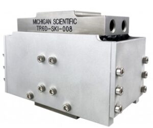
Three Directional Load Cells are ideal for measuring forces and moments. With high accuracy, wide range of capacities, and small size, our load cells are used in a wide variety of applications. Applications include measuring engine and motor mount forces in a vehicle, vehicle suspension forces, and test bench reaction forces. Rugged housing and temperature compensation ensure results in challenging conditions.

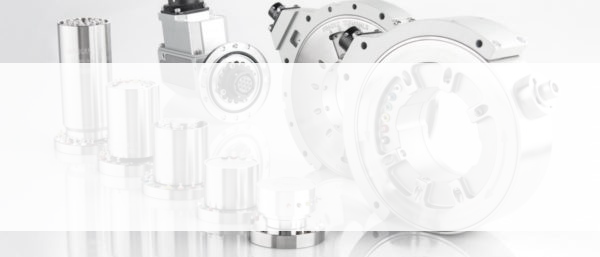
Wheel Force Transducers (WFTs) are used to measure vehicle reaction forces during durability and vehicle dynamics testing. Our WFTs are known for their durability, accuracy, simple installation, and ease of use. Installed on cars, SUVs, all sizes of trucks, ATVs, agriculture equipment and construction machinery, Michigan Scientific has a wide range of WFT capacities to fit almost any wheeled vehicle.

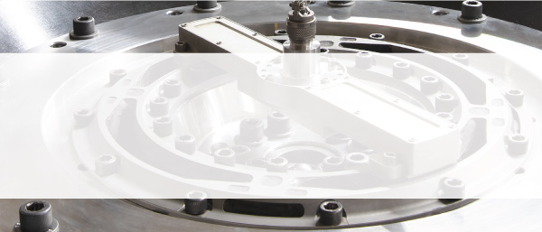
The utility of Michigan Scientific's instrument quality slip rings is unparalleled. The S-Series Slip Ring is capable of unlimited bandwidth and high-speed r/min. Our slip rings transfer signals in the harshest of conditions. They provide low-noise rotating connections for various sensors including strain gauges and thermocouples.