This project has taken a lot of time according to the calendar, but it’s finally completed. In a departure from my usual ‘build it as you need it’ approach, I made most everything before I began assembly so it’s just been a case of test-fitting, adjusting if necessary, then fixing in place.
Body and chassis permanently attached. Steps, couplers and brake hoses in place. Now testing the .020″ tarpaulin frames before cutting them to length.
I glued the door clasps (3mm channel) over the door openings before weathering the interior and the floor . I also fabricated and fitted the uncoupling levers. The brackets are 1.5 x 1.5mm .010″ styrene pieces and the lever is .010″ phosphor-bronze wire. I bent .020″ phosphor-bronze wire on a jig to create the tarpaulin frames. The main purpose of the frames is to support the wagon sides.
Door clasps sitting over the doors and uncoupling lever glued to the wagon end. Five tarpaulin frames mounted into holes on the top rails.
I created some advanced corrosion on the floor by dabbing neat isopropanol onto the surface which very quickly cut through the paint. I immediately dabbed rust coloured acrylic onto the exposed area. The brush picked up some of the isopropanol which then etched into the paint everywhere I dabbed the brush. Several more washes of grime and muddy brown were applied, with sufficient time between each wash for the previous one to fully dry. The key is to use plenty of water into which the thinned acrylic is dabbed. I think this is a very effective technique but probably one best used sparingly – too much of a good thing and all that. I decided against covering them with a tarpaulin at this point.
Door clasps in place and weathered. The floor is showing some serious corrosion towards the left hand end, but there are spots appearing elsewhere along the floor too.Side-on view of the completed model. I may add a bit more grime and surface rust to the sides to better match the interior.
Making this model spread across several months, but it probably took no longer than any other scratchbuild in terms of actual working time. I wasn’t in a hurry, or working to a deadline, so I worked on it occasionally rather than regularly. Gluing the styrene ribs inside and outside of each side and end was by far the most tedious task. Not being able to source or fabricate a more accurate triple-valve was frustrating but, in truth, it’s not easily seen and this is not a competition model. I am pleased with the finished appearance, most especially the corroded floor. This is the first time I’ve used the technique on such a large area and I’m very pleased with the result. Now, what to do next??
Work on the NODY since the previous post has focussed on the underfloor. Progress has been sporadic at best, as I’ve spent a lot time away from modelling. However, what time I have had for this project has been dominated by trying to get a reasonable representation of the underfloor pipework and details, especially the triple valve. Detailing a wagon chassis is always a frustrating process for me. First, it seems that plans and photos often don’t align, assuming plans and photos can be found at all. This time, photos have been useful adjuncts to the prototype plan that I have, but there appears to be some variation between individual wagons. Second, finding acceptable components is like seeking gold – hard to find and rarely where expected. Third, because of one and two, I’m rarely satisfied with the result. So it is with this model. I wasted too much time trying to source/contrive a reasonable approximation of a triple valve – I could find no useful photos and diagrams with which to fashion a model. I finally resorted to using the crude offering in the AR Kits underfloor details set. While the result may not bear close inspection, it is generally convincing from a distance, and painting and weathering can hide a multitude of sins.
The underfloor nearing completion.
Having got the underfloor to an acceptable state, it was time to glue the sides and ends together. A bit of fiddling and a couple of disassembled and reassembled joints got everything in order. Of greatest relief and satisfaction was that the floor/chassis unit slid perfectly into position first time – YAY!! AND, when sat on the bogies, the overall height above rail level was spot on.
Perched on its bogies to check total height (allowing for flange depth). Underfloor detail not yet completed.
The styrene sides are not rigid enough for my liking, and even though there are photos of the prototype that suggest that’s also the case with steel (lots of bent/buckled/warped sides), I always planned to support the model’s sides with the tarpaulin frames depicted on prototype plans. Only the first batch of 200 wagons were fitted for the tarpaulin frames, so I have numbered the model accordingly.
Approximate viewing angle when on the layout. Door clasps to be added, along with tarpaulin frames, steps, couplers and uncoupling levers.
I then added the final details to the underfloor.
The chassis with bogies screwed on. Footsteps will be fitted after the chassis has been sprayed and the coupler mounts are in place.An all-over coat of grimy black makes everything look neater. It will be weathered before I fit it to the body.
I fabricated six sets of footsteps from .015″ phosphor-bronze wire and fitted each to a 1.5mm styrene strip that will be glued behind the body shell.
I sprayed the scratchbuilt steps at the same time. They will be fitted after the floor and body have been joined. They will be picked out with thinned white per the prototype.
After I have weathered the chassis, I’ll glue it to the body. Then, the door clasps and uncoupling levers will be added before giving those and the top rails a coat of teal. Finally, I’ll add the couplers, brake hoses, tarpaulin frames and tarpaulins.
Lightly weathered chassis ready to be glued to the body.
At the end of the last post, I planned to assemble the NODY body. That hasn’t happened, because I awoke in the middle of the night with the idea that it would be ‘better’ to paint the sides and apply the decals before assembly. [I’m sure a hobby is supposed to bring relaxation and good sleep, not cause one to wake with wild ideas.] Anyway, the painting process took several days because I like to give paint plenty of time to cure. In the interim, I began work on the underframe. I cut the floor from .020″ sheet, and marked the longitudinal centre line, the mid-length line, and drilled pilot holes for the bogie mounts.
Two chassis rails were cut from .020″ styrene. I then glued a strip of scale 4×12″ styrene along the underframe centre line. This strip has a dual purpose: first, it adds a bit of extra rigidity to the floor/underframe and, second, it supports the chassis rails that are glued to each side and keeps them perpendicular to the floor. I then added 6mm lengths of 4×12″ strip between the chassis rails and centred on the bogie mount centres. I added enough pieces that the top was level with the chassis rails.
Chassis rails glued to the sub-floor. Checking bogie/wheel clearances.Styrene pieces glued between the chassis rail keep them vertical and evenly apart. Eventually, some heavy metal will be added between the rails to give the wagon some weight.
I then added the bolsters and support gussets. Scale 1×3″ stiffeners were added to the gusset edges. I even remembered to drill holes through the gussets and chassis rails, where appropriate, for brake piping and rigging before gluing them to the floor. The next task is to source or fabricate the various brake components and connect these with wire ‘piping’.
Bolsters and gussets in place. Gussets are .020″ styrene to which scale 1×3″ strips have been glued. Brake gear and piping positions marked to guide assembly.
I cleaned the sides and ends with IPA before spraying with light grey primer. This was followed with PTC blue. I found it difficult to get an even coverage with this colour. First, the ribbing seemed to create ‘shadows’ in the coverage as I sprayed along the sides (I should have sprayed up and down the ribs, not across). Second, I think I should have used dark grey primer as it would have visually lessened the impact of the ‘shadowing’. I intend to weather the wagon quite heavily so, hopefully, the flaws will be disguised effectively. A day later, I masked around the data and logo panels and sprayed them white, followed by clear gloss. Then, I worked the relevant decals into place, at which point I found that I had put the data panels on incorrectly (oops). There’s only 0.5mm difference between the panel’s height and width, but I couldn’t convince the decal to accept that. At this point, I also noticed that I hadn’t glued handrails/steps to a door on each side, so added them before spraying the sides with Testors dullcote. All up, this is probably my poorest paint job ever, but I hope the weathering will atone for that.
Sides with decals and additional handrails/steps (location determined from photos).
My plan, now, is to complete detailing the underfloor, before spraying it dirty black. Then, I’ll assemble the body and join it to the floor.
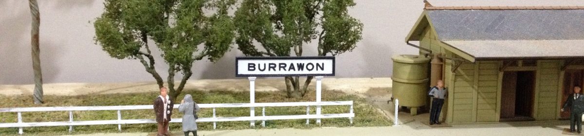
A simplified analogy for Chaos Theory is that the beat of a butterfly’s wings has impacts on large scale events. In other words, everything is interrelated. At the social level, people who flit from one task to another without actually committing or completing same are said to be butterflies. Things at Burrawon certainly have been chaotic of late and largely because of a butterfly – ie me. I’m not sure if I’ve lost my mojo but I certainly have been flitting about, starting projects here and there and generally making little true progress. Which brings me to my latest project – scratchbuilding a NODY wagon in HO scale. Why do that when there are perfectly good RTR examples available? Indeed, I have seven on the layout already. Well … errr … umm ….. it seemed like a good idea at the time. I’ll return to this later.
I am using styrene for the body. I began by cutting the sides and ends from .010″ pieces of styrene sheet to the correct length and depth. Then, I glued lengths of 1mm channel to the sides to represent strengtheners and door frames to the outer faces of each piece (1mm plain strip would have been just as effective). Next, scale 4×1″ styrene strips were spaced evenly between these. The process was repeated on the inner faces using 6×1″ strips staggered to represent the corrugated metal used on the prototype. The wider inner strips slightly overlap the outer strips suggesting the sheet has been pressed from one piece of material. The outer faces were completed with .005x.020″ strips glued along the bottom faces of the strips. There’s an awful lot of strips needed to cover two sides and two ends, inside and out. That ‘good idea at the time’ notion was questioned often. Taking regular breaks helped. I’m sure it will be worth it in the end.
Work in progress. Top Left: Outside face of wagon end completed. Top right: Inside face completed. Upper wagon side: outside face completed. Lower wagon side: inside face, strips yet to be added to door sections. Floor section at bottom of photo.
The sides and ends were topped with 2mm channel. The channel sits fully over the fabricated sides and ends. It adds significant rigidity to each piece, as well as visually. I decided to add the details to the sides and ends before gluing them together. I began with the door hinges. Each hinge consists of two lengths of .010x.020″ styrene strip, glued side by side and overlapping slightly at the hinge centre. I fabricated the door locks next. I used .005x.015″ strips for these.
2mm channel fixed to the tops of each piece. Outside faces: top and bottom left. Inside faces: top right and the side immediately below the ends.Cosmetic hinges of .010x.020″ styrene. (Don’t tell anyone, but the hinges on the right hand doors should be reversed – oops.)Door locks fabricated from .005x.015″ styrene strip.
Next the data and logo panels were cut from .005″ styrene and glued into position on each side. Finally, I used .010″ phosphor-bronze wire to represent the steps at each end of the sides, and the lashing rails along the sides and across the ends. I also drilled holes along the tops of each side for the tarpaulin frames. I plan to use these to support the sides.
Data panels in left-hand panel on each side. Logo panels in the panel left of centre. Handrails/steps and lashing rails of .010″ wire. Holes in lower, outer corners represent lifting lugs. A coat of primer and natural light from the side makes the details easier to see.
Locking bars are still to be added above the doors, but I won’t add those until the body is assembled. That way, I can sit the body top edges flat and square on a piece of glass while the sides and ends are glued together. So far, this has been a stop-go project. Hopefully, it will gain some momentum once assembly begins.
A trip to South Australia in search of inspiration.
I’ve been contemplating a new project for more than a year now. This is the result of several factors, not the least being the realisation that I get greatest pleasure from layout planning, scenery work and scratchbuilding. This epiphany, if it can be called that, has been reflected in my approach to Burrawon over the past eighteen months. While I’ve built items and done some scenic work, I’ve not actually operated the layout, save running the track-cleaning train every few weeks.
I am not abandoning Burrawon at this point. It has given me great pleasure over the past six years and I expect that will continue. However, I am looking for a new challenge. Building the diorama of my childhood train-watching site was a toe in the water of change. It provided some challenges and the opportunity to work with some new materials and techniques. So, what’s next? I have been impressed by narrow gauge model railways, particularly what’s being done with micro and mini-layouts. A key feature is the level of detail incorporated into every aspect of the layouts. Another, is that many are in the larger, less commercial scales such as O, F and G.
We’ve just spent a week in South Australia where we visited the Moonta Mines Museum and the Burra Mines site, as well as sampling and purchasing some liquid produce from the Clare region. Both Moonta and Burra have remains of copper mines that began in the mid-1800’s. Each site and others in the broader area were established by Cornish miners using, not surprisingly, techniques and equipment developed in Cornwall.
Moonta mines were underground affairs that operated from the 1860’s to 1923. The mines extended over generally flat country and were served by a narrow gauge railway. There was also a mainline railway nearby and the restored station building is included in the museum site. The museum boasts a narrow gauge line to take visitors around some of the mine sights.
Moonta: Richman’s mine engine house.Map of Moonta mines site (part) featuring the tourist railway route.
Mining at Burra began underground but evolved quite early to an open cut depth of 37 metres. Ore was first mined between 1845 and 1877 and again from 1971-1981. The Burra mines covered quite rugged country. An incline railway was used to draw material up the original open-cut slope.
Burra: engine houses and edge of open cut mine in foreground.Looking across the top of the Burra open-cut pit.
Aspects of each could be the basis of a mini-layout; I’m thinking 600x1200mm. To this end, I spent an afternoon at Moonta photographing and measuring structures and equipment that might be incorporated into a model. An immediate consideration is period. Modern – a tourist railway through ruins; or period – ore trains for a working mine? Scale and gauge? I’m leaning towards O-scale and 9mm gauge (On18). An appealing element of narrow gauge industrial modelling is that the scale/gauge issue is less rigid than for mainline modelling. Equally, rolling stock standards are also more free. Indeed, there is a photo in the Mines Museum of a very basic 0-4-0 locomotive designed and built in the mines workshop that just begs being modelled. Lots of thinking, plotting and consideration lies ahead.
Retro-fitting flashing crossing lights to the road over the quarry line
I received two Hand Made Accessories (HMA) flashing crossing lights, plus related paraphernalia, for Father’s Day. Fitting them was not a simple matter of removing the existing crossbucks and popping the lights in place because the quarry line sits directly above the helix. So, under-track access and clearances were immediate issues, as were locating the flasher box within reach of the wires from the lights, and running wiring from that to the AC supply. Those latter issues necessitated visiting the helix centre (read: crawling into that space).
Lights and flasher unit fresh out of their packs.
Having removed the existing crossbucks, I drilled holes to accept lengths of 7mm styrene tube. The tubes serve the dual purpose of raising the base of the posts to road level and providing a level surface upon which to sit the posts. In time, I will fit lengths of smaller diameter tube to the post bases which will slide into the 7mm tube to provide more support to the posts and allow the lights to be easily removed if necessary. I didn’t have the correct diameter tube to do that at this point.
7mm styrene tube cut to be flush with the lower surface of sub-roadbed and to raise the post bases to road level.The road is appreciably higher than ground level here, requiring a longer length of tube than on the other side of the crossing. Minimal disruption to existing ground cover, although the fence top rail copped a bit of damage.
Before fitting the lights, I made a couple of adjustments to the signs.
I added the numeral ‘1’ above ‘Tracks’ and painted over the ‘s’.
Having slid the wires through the tubes and mounted the lights, attention turned to mounting the flasher unit and securing wires that needed to run across the helix sub-roadbed. I built the helix with 20mm clearance between the tops of rolling stock and the bottom of the loop above, but I wanted the wiring securely out of the way. I used double-sided tape (rated to hold mirror glass to walls) for this, plus I covered the wires with a length of surgical tape.
Not pretty, but effective. The wires are sandwiched between double-sided tape and surgical tape. Those wires will never droop down into the path of trains on the helix.Wires connecting lights to the flasher unit (lower right). (The camera preferred to focus on the lit background than the dimly lit foreground.)
After a quick check that the lights flashed correctly, thoughts turned to automatic activation. The HMA activation unit relies on above-track mini reed switches. The switches are activated by a loco’s magnet (I wonder what happens if a train is hauled by two locos?).
HMA above-track reed switches.
I can’t say I like the switches, but the HMA instructions say they can be disguised by painting stripes across them to simulate sleepers. Also, being above track ensures that they are easy to fit (ignoring that holes have to be drilled for the wires and the need to keep the wires from fouling trains on the helix). However, before reaching for drill or paint, I plotted out where the switches would be placed.
Quarry side of the crossing: a reed switch under the loco’s front bogie would activate the lights just before a loaded train crossed the road, or deactivate the lights after a train had reversed across the road on its way to the loader. So far, so good.To ensure a train on the branch side of the road is clear of the crossing (either coming or going), the reed switch would need to be placed beyond the quarry line junction with the branch line proper (ie in front of the loco) . Not good.
Having a reed switch on the branch line proper would lead to the lights being activated by trains heading to, or from Burrawon, as well as quarry trains. A solution to that issue would be to activate the reed switch for quarry trains only. This could be most easily done by controlling power to the reed switch with a toggle switch, effectively making it a manual operation. Thus, the most convenient means of activating the crossing lights is by manually flicking a toggle switch – no need for reed switches, activating unit, drills, wiring or paint. An analogue solution to a digital dilemma. I’ll take it.
Did Smithy the farmhand make it across the line before the lights began flashing? Or, did he mistime his take-off after the train passed? We’ll never know.
We had a contractor here last week bringing the cattle yard into the 21st century with a new crush and other items. Each evening he’s taken his tractor home but left the small bucket that he’s been using. It occurred to me that this would make an interesting addition to the quarry. Sometime ago, I bought an earthmover, but it was too large for the scene and also out of period, so a bucket will suggest heavy plant in the quarry scene without overwhelming it.
I began by photographing and measuring the bucket. I toyed with making the model from metal, but ultimately chose styrene for ease and speed of construction. I began with the bucket back and base as a single piece, to which I then added the sides.
I temporarily joined two pieces of .010″ styrene, back to back, and then shaped the sides.Sides added to base and back.The bucket sides consist of several elements that allow the bucket to perform multiple tasks such as material collection through the front and material distribution either by tilting the bucket or opening a gap between the bucket base and back.Bucket side (left), hydraulic drive arm (right).Details added to basic bucket: strengtheners along bucket front and sides, drive arm, hydraulic mounts and channel across bucket top to protect hydraulic hoses.Bucket back showing mounting brackets, hydraulic pistons and hoses.Side view including strengthening along front edge, hydraulic hinges and mounting brackets.Hydraulic pistons of phosphor-bronze wire partially coated with plastic sheath.Hydraulic hoses of 0.2mm copper wire (strands from multistrand dropper wire).
The project took less than a day to get to this point (including disruptions and other commitments). All that’s needed now is painting and weathering. Oh, and finding the most convincing position within the quarry scene.
Still assessing different locations within the quarry scene.
GJ Churchward designed the 45xx/55xx class 2-6-2T prairie tanks for branchline work. The first 75 (4500-4574) had flat top 1000 gallon tanks. Number 4575 and onwards had taller 1200 gallon tanks that angled downwards over the front half of each tank. Around 1990, I set out to build both versions of the class, but only finished the 1200 gallon version (4582). At that time, we moved houses several times in quick succession, ultimately moving from Brisbane to Townsville where priorities changed, along with family and work demands. These factors combined to end my 2mm modelling pursuits.
Fireman’s side. All fittings turned by hand. Handrails of brass wire held in place with twisted wire knobs.
Every once in a while I have taken the loco’s out of their storage box and parked them on a short length of display track. Recently, I decided to get them running again, which first necessitated construction of a length of track that can be powered (I didn’t try to power the display track that is a series of 150mm lengths of rail). Briefly, I found a length of display-quality timber lurking in the shed, on which I stuck some 2mm scale PCB sleepers to which I soldered two lengths of Code 55 rail. Finally, I ballasted it with fine real dirt, which I gave a wash of dirty black acrylic. One day I might even paint the sleepers.
Outside steam pipes, smokebox stays, curved drop end. Hand-turned buffers and coupling hook.
Back to the Prairie tank. I have always considered this to be my best 2mm model. I had added more fine detail to it than the previous loco’s and it was the only one that was airbrushed. I had also managed to make it a very smooth runner …. until I realised that I’d forgotten to fit brake gear. My modelling time was limited at that point in my life, so instead of dismantling the model, I rushed in and drilled holes in the chassis frames for the brake hangers. The result was that my previously smooth runner now ran like a three-legged dog. I suspected that a piece of drill swarf had got into the gearing, but didn’t have the time to fully resolve the issue, so it went into the storage box and never run again.
Tank top detail includes tank filler caps, breathers, lifting rings, fire-iron bracket in front of the cab (left tank), top-feed piping, whistles, handrails. Real coal in the bunker.
Recently, thirty-five years on, I decided to resolve the situation, so I dismantled and rebuilt the gearbox. While I didn’t find a definite cause of the problem, I did find that one of the idler gears was not square on its muff, so I replaced both the gear and the muff. I also checked the driving wheel quartering which was okay, but one pair of drivers was tweaked a smidge. Things ran smoothly upside down on the benchtop, but sucked when placed on the track. This was due to light corrosion on the steel tyres on the wheels (the 2mm Scale Association had, for a short period, changed from cast metal spokes with nickel-silver tyres, to plastic spokes with steel tyres for reasons I cannot remember). I managed to improve electrical pick-up by rubbing the tyres with WD-40 and a toothpick until the corrosion was largely eliminated.
The motor, split-frame chassis, gearbox and front and trailing trucks as disassembled. The cylinder block is perspex filed to shape. Note the light corrosion on all wheels. The less than pretty underbelly after refurbishing. Electrical pick-up is from all wheels. Phosphor-bronze wires on the pony and trailing trucks serve as both springs and power transfer to the chassis.
I also serviced the motor and replaced the brake gear while I had the loco apart. The penultimate task was refitting the chassis to the body. Finally, I fitted the valve guide brackets to the piston assembly. I can’t remember the technical name for those, but they can make or break a model, either visually by their absence, or mechanically by their presence – ie interfering with the smooth motion of the crosshead along the piston guides. Getting the two brackets accurately aligned is a fiddly but important task. The loco needs to be run-in (not possible on a 600mm length of track) but it runs much better than it did thirty-five years ago.
Reassembled and with valve guide bracket in place. The connecting rods, crosshead and bracket were fettled from nickel-silver bar. Note bars on rear windows, steps on bunker end, vacuum pipe on buffer beam and sandbox and pipe between the footsteps and rear driver.Driver’s side. Note brake hangers, shoes and rodding.
The Churchward small prairie tanks were pretty machines and I think the model depicts this well (shame about the crude transfers of 40+ years ago).
Back in the mid-1980’s, I commissioned a series of etched brass kits in 2mm scale, in collaboration with Stuart Hine. Stuart had originally produced the artwork in 3mm scale. However, it wasn’t simply a case of photo-reducing the 3mm artwork, as some of the smaller items would not have survived the etching process. So, Stuart needed to adjust the diagrams to account for this. My role in the collaboration was as enabler/financier. The etching company required a minimum number of units well beyond what Stuart and I needed, so the remainder went to the 2mm Scale Association shop. One set of etches was a sheet of four GWR 57′ toplight coaches – brake-third, first/third composite and all third (x2). These built into very nice representations of the prototype. I went a bit overboard and included interior details including corridor and compartment walls and seating coloured appropriately for each class – none of which can be easily seen but, importantly, gave the models a bit more rigidity and weight. I described these in some detail in ‘Another world of modelling – 3’ (June 2, 2023).
Four of the rake of ten coaches made in the late 1980’s.Brake-third, compartment side. Note the brass grab-handles beside each door (except the guard’s door. The guard had to make do with a straight vertical handrail low down on the door, presumably to assist climbing up and down to track level). I made each grab-handle by bending brass wire around a purpose-made former.
While I was making the rake of ten 57-footers, I thought it would be an interesting project to make a 70′ version of an all-third coach. This meant adding two more compartments to the existing etch by cutting an etch in two and inserting a two-compartment section from another etch. The best way to do this was by cutting along the door lines. So, the piece to be inserted began and ended at a door, ie door, compartment, door, compartment, door-post. This ensured that the insert was square and consistent in length and the joint could be hidden within the door lines. The procedure worked well, although a few scale inches were ‘lost’ in cleaning up the cut edges and preparing them for soldering. By inserting the extension towards the centre of the coach, I was able to use the etched locators for the bolsters, queen posts, and other underbody details.
Extended body. Inserted compartments between 3rd and fifth doors from the right.Underfloor detail includes brake cylinders and piping, battery boxes, generator, queen posts and rods.
An alternative approach would have been to cut two etches each at the fifth door and join those two sections together. This would have required just one joint instead of the two described above. There must have been a reason I didn’t do that, but it’s been lost in the mists of the past thirty-five years.
I could not cut and join the roof etches because the rain strips are curved over their entire lengths. So, I fabricated a roof from scratch. Forming the rain strips was especially difficult and it took several attempts to get an acceptable result. Looking at it now, it actually looks better than I remember, but I think I’ll try a different approach to see of I can get an even better result.
The scratchbuilt roof looking a little worse for wear after floating around in the carry case for 35 years.
Anyway, that’s where I got to all those years ago before multiple cities and house moves, family and work demands, not to mention a change of scale and outline, led to the project being shelved. I now have the time and the will to complete the project, if for no other reason than to say I completed it. Onwards!
This is the last in the series on building the new goods shed. It covers fitting the roof and trusses, along with interior lighting, gutters, downpipes and other details. I began by adding a few more details within the shed before fitting the roof trusses.
Additional items on the deck include stored milk churns, hay, bags of potatoes and pallets. The roof trusses and ridge beam are in place. Three non-functioning light fittings hang from the lower beam. Note the LEDs near the ridge beam – more about them later.
We’ve been having fairly typical autumn weather of late, most especially great swings in humidity. I noticed that the wall sections (as separate items) bowed considerably every time the humidity rose. I assume the stained scale lumber was swelling with the humidity and then shrinking as the humidity dropped. I’m modelling the shed as a long-standing structure, but I didn’t want it to look like it was on its last legs, so I sealed the lumber with clear coat (on a low humidity day). That nearly eliminated the bowing, but to keep the sides straight on the finished model, the wall base-plates were glued to styrene strips set on the styrene base. At the wall tops, I added small braces to each truss to hold the sides the correct distance apart.
Styrene strips to which the wall base-plates will be glued. The rail side wall base-plate will be glued to the timber deck atop the masonry base.Braces glued under the trusses to keep the wall tops straight.
I attached two Noch room LEDs under the roof to illuminate the interior details. The LEDs are chunky but effective, and they can’t be seen where I placed them high up in the roof space. I fitted them to short lengths of scale lumber and ran their wires through lengths of styrene tube fitted between the trusses. This kept everything neat and out of sight. I originally planned to run the wires under the roof and down a piece of brass tube, dressed up as a power pole, just outside the building. That arrangement did not look convincing, so I bit the bullet and drilled a hole up through the styrene base and the deck. I managed to achieve this without any visible damage – the hole is in the corner of the office that cannot be seen.
LEDs supported by short lengths of scale lumber glued to adjoining trusses. The clips are holding painted tube to a truss chord while the glue sets. The original plan was to run the wires under the roof to a brass tube just outside the building. Fortunately, some ‘bravery’ with the drill yielded a better result.The finished roof. I weathered the roof sections before fitting them to the trusses. The skylights are 0.005″ clear styrene supported by an internal frame of scale lumber between pairs of trusses. Barges and cap timbers were painted before fitting. A ridge former of 1mm styrene rod sits between the top edges of the roof sections. Capping and flashing is represented by 3mm wide strips of cigarette paper soaked with matte medium.Railside wall and station end. Gutter and downpipe fitted. The downpipe is held by Keiran Ryan etched brass astragalsRoad side wall and yard end. Gutter, downpipe and vehicle guard under side door. Wires for interior lighting yet to be redirected inside the building.In place on the layout. Yard end landing and steps added.The new shed adjoins the outside deck, made in-situ, board by board, for the previous shed.
And now for a couple of atmospheric shots of the interior.
Looking through the building from the station end.Inside as seen from a wagon-mounted camera.
Overall, I’m pleased with the building. Externally, it’s not greatly different from its predecessor but, internally, it’s a real improvement.