‘Yes Virginia, there really is a Father’s Day!’

Retro-fitting flashing crossing lights to the road over the quarry line

I received two Hand Made Accessories (HMA) flashing crossing lights, plus related paraphernalia, for Father’s Day. Fitting them was not a simple matter of removing the existing crossbucks and popping the lights in place because the quarry line sits directly above the helix. So, under-track access and clearances were immediate issues, as were locating the flasher box within reach of the wires from the lights, and running wiring from that to the AC supply. Those latter issues necessitated visiting the helix centre (read: crawling into that space).

Image
Lights and flasher unit fresh out of their packs.

Having removed the existing crossbucks, I drilled holes to accept lengths of 7mm styrene tube. The tubes serve the dual purpose of raising the base of the posts to road level and providing a level surface upon which to sit the posts. In time, I will fit lengths of smaller diameter tube to the post bases which will slide into the 7mm tube to provide more support to the posts and allow the lights to be easily removed if necessary. I didn’t have the correct diameter tube to do that at this point.

Image
7mm styrene tube cut to be flush with the lower surface of sub-roadbed and to raise the post bases to road level.
Image
The road is appreciably higher than ground level here, requiring a longer length of tube than on the other side of the crossing. Minimal disruption to existing ground cover, although the fence top rail copped a bit of damage.

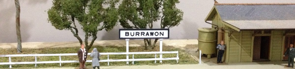
Before fitting the lights, I made a couple of adjustments to the signs.

Image
I added the numeral ‘1’ above ‘Tracks’ and painted over the ‘s’.

Having slid the wires through the tubes and mounted the lights, attention turned to mounting the flasher unit and securing wires that needed to run across the helix sub-roadbed. I built the helix with 20mm clearance between the tops of rolling stock and the bottom of the loop above, but I wanted the wiring securely out of the way. I used double-sided tape (rated to hold mirror glass to walls) for this, plus I covered the wires with a length of surgical tape.

Image
Not pretty, but effective. The wires are sandwiched between double-sided tape and surgical tape. Those wires will never droop down into the path of trains on the helix.
Image
Wires connecting lights to the flasher unit (lower right). (The camera preferred to focus on the lit background than the dimly lit foreground.)

After a quick check that the lights flashed correctly, thoughts turned to automatic activation. The HMA activation unit relies on above-track mini reed switches. The switches are activated by a loco’s magnet (I wonder what happens if a train is hauled by two locos?).

Image
HMA above-track reed switches.

I can’t say I like the switches, but the HMA instructions say they can be disguised by painting stripes across them to simulate sleepers. Also, being above track ensures that they are easy to fit (ignoring that holes have to be drilled for the wires and the need to keep the wires from fouling trains on the helix). However, before reaching for drill or paint, I plotted out where the switches would be placed.

Image
Quarry side of the crossing: a reed switch under the loco’s front bogie would activate the lights just before a loaded train crossed the road, or deactivate the lights after a train had reversed across the road on its way to the loader. So far, so good.
Image
To ensure a train on the branch side of the road is clear of the crossing (either coming or going), the reed switch would need to be placed beyond the quarry line junction with the branch line proper (ie in front of the loco) . Not good.

Having a reed switch on the branch line proper would lead to the lights being activated by trains heading to, or from Burrawon, as well as quarry trains. A solution to that issue would be to activate the reed switch for quarry trains only. This could be most easily done by controlling power to the reed switch with a toggle switch, effectively making it a manual operation. Thus, the most convenient means of activating the crossing lights is by manually flicking a toggle switch – no need for reed switches, activating unit, drills, wiring or paint. An analogue solution to a digital dilemma. I’ll take it.

Image
Did Smithy the farmhand make it across the line before the lights began flashing? Or, did he mistime his take-off after the train passed? We’ll never know.

A new goods shed for Tarawangan – 6

Completing the shed.

This is the last in the series on building the new goods shed. It covers fitting the roof and trusses, along with interior lighting, gutters, downpipes and other details. I began by adding a few more details within the shed before fitting the roof trusses.

Image
Additional items on the deck include stored milk churns, hay, bags of potatoes and pallets. The roof trusses and ridge beam are in place. Three non-functioning light fittings hang from the lower beam. Note the LEDs near the ridge beam – more about them later.

We’ve been having fairly typical autumn weather of late, most especially great swings in humidity. I noticed that the wall sections (as separate items) bowed considerably every time the humidity rose. I assume the stained scale lumber was swelling with the humidity and then shrinking as the humidity dropped. I’m modelling the shed as a long-standing structure, but I didn’t want it to look like it was on its last legs, so I sealed the lumber with clear coat (on a low humidity day). That nearly eliminated the bowing, but to keep the sides straight on the finished model, the wall base-plates were glued to styrene strips set on the styrene base. At the wall tops, I added small braces to each truss to hold the sides the correct distance apart.

Image
Styrene strips to which the wall base-plates will be glued. The rail side wall base-plate will be glued to the timber deck atop the masonry base.
Image
Braces glued under the trusses to keep the wall tops straight.

I attached two Noch room LEDs under the roof to illuminate the interior details. The LEDs are chunky but effective, and they can’t be seen where I placed them high up in the roof space. I fitted them to short lengths of scale lumber and ran their wires through lengths of styrene tube fitted between the trusses. This kept everything neat and out of sight. I originally planned to run the wires under the roof and down a piece of brass tube, dressed up as a power pole, just outside the building. That arrangement did not look convincing, so I bit the bullet and drilled a hole up through the styrene base and the deck. I managed to achieve this without any visible damage – the hole is in the corner of the office that cannot be seen.

Image
LEDs supported by short lengths of scale lumber glued to adjoining trusses. The clips are holding painted tube to a truss chord while the glue sets. The original plan was to run the wires under the roof to a brass tube just outside the building. Fortunately, some ‘bravery’ with the drill yielded a better result.
Image
The finished roof. I weathered the roof sections before fitting them to the trusses. The skylights are 0.005″ clear styrene supported by an internal frame of scale lumber between pairs of trusses. Barges and cap timbers were painted before fitting. A ridge former of 1mm styrene rod sits between the top edges of the roof sections. Capping and flashing is represented by 3mm wide strips of cigarette paper soaked with matte medium.
Image
Railside wall and station end. Gutter and downpipe fitted. The downpipe is held by Keiran Ryan etched brass astragals
Image
Road side wall and yard end. Gutter, downpipe and vehicle guard under side door. Wires for interior lighting yet to be redirected inside the building.
Image
In place on the layout. Yard end landing and steps added.
Image
The new shed adjoins the outside deck, made in-situ, board by board, for the previous shed.

And now for a couple of atmospheric shots of the interior.

Image
Looking through the building from the station end.
Image
Inside as seen from a wagon-mounted camera.

Overall, I’m pleased with the building. Externally, it’s not greatly different from its predecessor but, internally, it’s a real improvement.

A new goods shed for Tarawangan – 5

Every little bit counts.

I completed fitting corrugated metal to the shed walls and roof sections – not without having to scrap and re-do a couple of rows. They were my errors, so I own those, but I am disappointed with the quality of the corro’ metal sheet I have received. The quality and consistency has, I feel, deteriorated since the last time I used that particular product. I ended up scrapping about 20-30% of what I purchased before giving up on trying for consistent quality and accepted what was on offer. Rant over. That experience slowed progress for a few weeks while I considered how to move forward and to regain momentum. However, it didn’t stop me from working on other items including doors and windows and, once finished, painting and fading the corro’ walls. Let’s start with the walls.

Image
End wall airbrushed with Tamiya ‘light grey’. Scale lumber trims added around openings.
Image
I ‘faded’ the paintwork by brushing IPA randomly over individual sheets and then drawing a dry flat brush along each sheet. This partially removed some of the top coat and exposed the undercoat. The Tamiya light grey has a blue base, so the change in tone between sheets is quite effective. Sadly, the photo doesn’t do the result justice.
Image
Next the windows were fabricated board by board. The glazing is Evergreen .005″ clear styrene. This photo demonstrates the ‘fading’ more clearly on the roadside wall.
Image
A window on the roadside wall outside face. I’ve put a fair bit of effort into fabricating the windows. The glazing was first cut to fit snugly within the window space. I then glued scale timber framing in front of and behind the glazing.
Image
The inside face of the same window.

Next up were the doors, again fabricated board by board. I also fabricated runners and rollers for the large sliding door on the roadside wall (left), and a runner for the small sliding door on the railside wall (right). Each sliding door has a large metal handle, of 0.4mm nickel-silver rod, fitted on the interior side only (yet to be painted). The two doors in the centre are for each end wall. I fabricated and fitted door knobs for each. They will be attached to dummy hinges.

Image

I weathered these items with charcoal. I think it is a good representation of dirt and dust. On the walls I concentrated on getting the charcoal on the top surfaces of the frame timbers as well as low down on the walls. I rubbed 240 grade emery cloth horizontally across the sliding doors to represent the score marks commonly seen on such doors. They were also brushed with charcoal, particularly the lower halves.

Image
Inside face of end wall after brushing with charcoal.
Image
Doors after charcoal applied.
Image
Finally, assembly begins! The down end wall and roadside wall being held together while the glue sets.
Image
Deck and office fixed to walls. Angle braces at wall tops in place. Doors and a few detail items on the deck.
Image
A lower angle view of the roadside wall, deck and office. The large sliding door is fully open – a slight miscalculation on my part, as I would have liked a little of it visible from the outside.
Image
Railside wall and narrow walkway.

I’m pretty happy with progress. Just trusses, lighting, roof and final details to go.

What to do while waiting for glue to dry on a big project?

Something to amuse oneself.

While waiting for glue to dry on the goods shed project, I cast around for a small task that could be interrupted frequently. I had a couple of sets of Anton’s yard lamps which fitted the bill perfectly. Not a big task – clean up and paint the lamp castings, stain the wooden posts, glue the lamps to the posts, add a bit of weathering. However, photos of the prototype suggested that the lamps were held to the posts with metal strapping/brackets. I decided to use some Keiran Ryan astragal etches to represent these – not prototypical, but pretty good representations. Then, I thought that the flat bases to the lamp covers looked a bit flat = featureless. So, I decided to represent bulb ends by dabbing a little canopy glue onto the centre of each lamp housing. I’m happy with the result, but I wonder how many viewers will notice that. Anyway, I had fun and isn’t that what a hobby should provide?

Image

The prototype posts have fancy little caps. The posts supplied with the Anton’s sets are reduced at one end, which I assume is to represent the caps. I wasn’t convinced by those, so the next little project will be to turn some little caps to glue to the post tops. Sounds like another little task while glue or paint is drying on a project.

A new goods shed for Tarawanagan – 4

Adding external cladding

Having completed the internal framing for the walls, it’s time to add the external cladding of individual, scale-sized sheets of corrugated metal. I’ve mentioned before my dilemma regarding the use of individual sheets of corrugated metal (ie whether the result with its oversize gaps and joins is more convincing/realistic than continuous runs of material with no joins and overlaps). Anyway, I hope to produce a neater finish by doing just one row of sheeting a day. That way, the adhesive will have time to fully cure before the next row is added. This will require masking each wall multiple times, but the benefit is that the adhesive can be sprayed onto the overlap strip for each row, resulting in tighter overlap joins and, thus, a more convincing result. Here goes!

I first cut many scale-size sheets of corrugated metal using a jig to keep everything accurate and uniform. I then drew vertical and horizontal placement lines on each wall. Then I was ready to mask the wall prior to spraying contact adhesive onto the styrene and the corro’ sheets.

Image
My cutting jig. Its main purpose is to consistently size each piece (saves measuring each piece). The corrugated metal strips were squared and trimmed before cutting the individual sheets. The styrene cover plate holds the metal in place, and can be tweaked slightly to ensure that the cut is exactly along a corrugation.
Image
The end walls masked prior to spraying the first row of each with contact adhesive. They have been marked horizontally and vertically to guide placement of individual sheets,
Image
The section of the sheets that will be overlapped by the top row will be sprayed with contact adhesive. This helps sit the overlapping sheets more firmly onto the underlying sheets.
Image
The remainder of the wall is masked before spraying the contact adhesive.
Image
All sheets in position and openings cut in the metal. The edges will be tidied when the timber frames are fitted. I can’t say it’s a pretty look at this point. Hopefully, a coat of grey primer will improve the appearance.
Image
I’m going to tell myself these look better painted, although I can now see that a couple of sheets have moved while I was trimming them.

Each of the side walls has two rows of sheeting – that’s 120 individual sheets in total (Let’s not mention the roof sections yet.). I’d best get started.

A new goods shed for Tarawangan -3

The internal deck – an exercise in persistence.

I began construction by gluing the long deck timbers together, board by board. Indeed, this part of the project was characterised by bouts of gluing many pieces of timber together consistently and accurately, and waiting for glue to dry. I then glued the joists to the deck at approximately 18 scale inch centres. When all the joists were in place, I scored the deck timbers to represent joins above random joists. Finally, I glued the bearers to the joists.

Image
Gluing the deck timbers together. Slight dimensional variations between boards resulted in a difference of approximately 1mm in total width of the deck from one end to the other. This was eased out with some judicious sanding of the broad edge timbers.
Image
The joists were added from each end, working towards the centre. A strip of styrene was used to space the joists at 18 scale inch centres.
Image
The other end with two joists in place. The cut-out in the top right corner is for a set of stairs, as at the other end also.
Image
Getting there – piece by piece. The timber to the right of the styrene spacer has just been glued in position. I triple check that the joists are square and evenly spaced by first using the styrene spacer to consistently set the distance between each pair of joists. I then use a set-square to ensure that each joist is square to the deck edge. Finally, I check that the inner-most joists of each of the two sets are parallel to each other. Just another 12 joists to set in place.
Image
The set-square ensures each joist is square to the deck’s longitudinal axis.
Image
All the joists in place. Time to sand the joist ends and check that it fits squarely inside the building.
Image
Checking the deck is square within the walls. Styrene strip is supporting the deck at the correct height above ground level. Ultimately, lengths of square-section styrene will be used to represent the brick footings/piers under the bearers. The shed office walls are temporarily in place in the corner. More about that later.
Image
Fitting the bearers. The steel bar holds the bearer vertical to the joists, and the bearer is kept straight against the bar with clips.
Image
Masonry pillars to support the deck glued to .030″ styrene sheet. The upper two rows are per the plan. The bottom row of three support a bearer that is not on the plan. I added it to support the deck near the road-side wall. Its purpose is purely pragmatic (ie function over form).
Image
Each pillar is styrene strip wrapped with brick paper.
Image
The styrene strips will keep the side and ends from bowing. The strips will be hidden by the deck.

That completes all the internal structures. Details such as doors, windows, etc will come later. The next step is to glue the individual corrugated metal sheets to the walls and roof sections. Best get cutting the sheets in preparation.

A new goods shed for Tarawangan – 2

Cutting and framing the shed walls.

I have built several sheds with corrugated metal glued directly to the wall framing (be that styrene or timber), but I wasn’t confident that a building of this size, located close to the layout’s edge would be sufficiently strong to withstand accidental contact. So, I decided to strengthen the walls and roof with corrugated styrene sheet inside the corrugated metal sheets. Thus, the walls and roof have both internal and external corrugated surfaces. The downside of this strength is that the walls are about .060″ thick. However, the external dimensions are correct. I began by cutting the styrene walls to size and then opening window and door spaces using the score and snap method.

Image
The shed side walls with window and door openings marked. The lines around and the crosses within the openings indicate score lines along which the sheet will be snapped.
Image
The openings will be cleaned and squared prior to fitting the corrugated metal sheet.
Image
Framing on the roadside wall. (Although the model is straight and square, I have noticed that this camera distorts images by making long straight lines look curved. This is particularly evident in this image. An alternative possibility is that I am not using the camera correctly. )
Image
End walls were first cut as rectangles, then a truss was used to set the roof profile.
Image
Then the door openings were made.
Image
The ends with framing and trusses added.
Image
The walls and ends taped together to check the model’s footprint matches that of the existing shed. Cross-bracing on the rail-side wall yet to be added. Door and window framing will be added before the corrugated metal is glued to each wall.
Image
The rail-side wall of the shed at Tarana had a masonry section below the loading deck level. Photos suggest it was industrial brick. I’m toying with making it resemble poured concrete.
Image
I made the masonry section of thick styrene strips.
Image
Here it is in cross-section.

I’m pleased with progress to date. I have been taking my time with this project and enjoying each part of it. Speaking of which, the next item will be the interior deck and associated fittings – all of it will be board by board construction.

There’s a prototype for everything

so they say

When I was scratch-building the wooden trestle bridge for my neighbour’s layout, I noticed, as I set a wing post in place, that it was misshapen. My immediate response was to scrap it, until I remembered that there were misshapen wing posts on the very prototype upon which I have based the model.

Image
This ballasted deck bridge is on the disused Bombala line.
Image
Both wing posts on this bent look very agricultural.
Image
The offending post on the model is much less dramatic than on the prototype.

A new goods shed for Tarawangan

Scratchbuilding a timber framed, corrugated iron structure

I built the existing goods shed at Tarawangan over five years ago. I used a couple of photos of the shed at Tarana, taken during the 1960’s and early 1970’s to scale out the key dimensions. I then built a card mock-up to assess the accuracy of the dimensions and the physical impact of the structure within the Tarawangan yard area. At 80 scale feet, it looked too long for the site – not that it wouldn’t fit within the site but, rather, it overwhelmed the area visually. Reducing it to 60 scale feet kept the general appearance of the structure and visually set it more comfortably within the broader scene. To be clear, I never intended to model Tarana’s shed faithfully, merely reflect its key external features. I think the existing model does that adequately, but I’ve always harboured a desire to make a more accurate model of the interior.

Image
The existing shed.

To aid that desire, I purchased the Data Sheets plan of the NSWR standard G5 design of 1875. The plan is based on the sheds at Yass and Gunning. The plan confirmed the key dimensions that I had scaled from the photos, so the same footprint can be used for the upgraded model. One thing I have noticed about NSWR ‘standard’ designs, be they buildings, footbridges, or stocking yards, is that they appear to be honoured more in name than in the completed product. For example, Tarana’s shed had swing doors at each end compared to sliding doors on the Data Sheets plan. The Tarana shed also had a door on the rail side wall, and the lower section of that wall was masonry rather than corrugated iron. Those differences may reflect that Tarana’s shed was built when the Oberon branch was constructed (circa 1920) so perhaps to a later standard. Photos of Tarana yard suggest that the shed was demolished sometime in the 1970s but the doors at each end had been removed before then.

Image
Tarana’s shed in 1967. The swing doors at this end have been removed. Note the masonry base on this side and the door midway along the wall. The door to the shed office is behind the wagon. Note also the two dark areas in the roof which I chose to model as skylights.

I built the shed as a styrene shell to which corrugated metal was glued. The corrugated metal was applied in strips, rather than as individual sheets. I believe that the overlap gaps between individual sheets on a model are more obtrusive and thus less realistic, than is the absence of individual sheets. Indeed, the prototype photo demonstrates that vertical overlaps are much less obvious than the horizontal overlaps purely because of light and shadow effects. Although I am still of that belief, from a viewing standpoint, I have ceded to the notion that using individual sheets produces a more ‘authentic’ model.

Image
Styrene shell
Image
Corrugated metal glued to shell.

I added some interior framing to the goods shed walls. However, the inside walls are plain styrene not corrugated metal as they should be. The roof has five, triangular sheet styrene pieces to give it strength and allow it to be removed.

Image
Shed interior. Basic framing glued to plain styrene shell. The hefty construction is evident. One advantage of this approach for a model so close to the front edge of the layout is that cannot be easily damaged.

Q: why would I replace the existing shed which is visually satisfactory and reasonably resistant to damage? Insanity? Too much time on my hands? Seeking a new challenge? Trying to extend Burrawon’s lifespan by updating features?

A: Probably a combination of all these, plus I’ve always wanted to give the shed proper roof trusses and wall framing. It’s also an opportunity to detail the interior and add some lighting. No surprise then that I began by building the roof trusses. Six were required, so that called for a jig.

Image
Six trusses of stained scale lumber, plus jig. Staining the wall framing lumber is under way.
Image
Hmm? Perhaps a new roof would suffice? Nah, look at all that thick styrene. Got to go the whole hog now.

The next step, then, is to assemble the wall framing, and the internal decking, and the office, and put it all altogether, and sit it in place. How hard can it be? More importantly, how long will it take?

Ballasted deck trestle bridge

nearing completion

The bridge that I’m building for my neighbour’s layout is now fully assembled. Since the previous post, I have prepared and added concrete footings to the bases of the bents, constructed two end piers that will be nearly fully buried in the scenery, and glued the deck to the bents. There’s just the weathering and scenic work to do now, and then building timber retaining walls/abutments just behind the end bents – a task that will be undertaken in-situ.

Image
The footings are 4x5mm wood coated in Spakfilla and then coated with aged concrete acrylic. I think that commercially available aged concrete is too yellow for Australian concrete, so these will be given a grey wash before weathering with stains and powders.
Image
The assembled bridge sitting on the foam construction support.
Image
Side-on view.
Image
Looking through the bents.
Image
Design a site like this with WordPress.com
Get started