Basic Setup:
Arduino Mega w ESP 8266
CNC Shield
Arduino Nano on Print head
4 x LDO6AJSA LED Driver boards link
4 x 3W 380nm UV LED link
1 x Heatsink link
I. System Architecture Diagram
The system operates across three distinct tiers, separating the user interface, the motion control, and the real-time hardware execution.
======================================================================
TIER 1: THE NETWORK HUB (ESP32)
======================================================================
[ Web Browser ] --> HTTP POST (JSON) --> [ ESP32 Web Server ]
- User draws UI - Broadcasts standalone AP
- Sends gridData - Hosts index.html & app.js
- Converts JSON to Hex
|
| Serial2 (115200 Baud)
| TX/RX Protocol
v
======================================================================
TIER 2: THE MAIN BRAIN (Mega 2560 + CNC Shield)
======================================================================
[ Arduino Mega 2560 ] <----> [ Hardware Peripherals ]
- Parses Hex image data - X, Y, Z Stepper Motors
- Calculates Mesh Bed - SSD1306 OLED Screen
Leveling (MBL) - SD Card (Config & Mesh Storage)
- Orchestrates X/Y motion - User Input Buttons
|
| Serial1 (115200 Baud)
| TX/RX Protocol
v
======================================================================
TIER 3: THE PRINTHEAD MCU (Nano Custom PCB)
======================================================================
[ Arduino Nano ] <---------> [ Printhead Hardware ]
- Real-time peripheral device - D10, D11, D12, D13: 4x UV LEDs
- Never blocks UART - D3, D7: CR Touch (Servo & Signal)
- Microsecond timers - A0-A5: TMP36 Temp Sensors
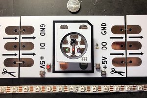
- D8: NeoPixel Status Indicator
======================================================================
I. System Architecture
The system operates across three distinct tiers, separating the user interface, the motion control, and the real-time hardware execution.
TIER 1: THE NETWORK HUB (ESP32)
- Input: Receives HTTP POST (JSON) from the User's Web Browser.
- Core Functions: * Broadcasts a standalone Wi-Fi Access Point.
- Hosts the index.html and app.js frontend files.
- Converts the JSON pixel arrays into Hexadecimal strings.
- Output: Sends data down to Tier 2 via Hardware Serial2 (115200 Baud).
TIER 2: THE MAIN BRAIN (Arduino Mega 2560)
- Hardware Attached: CNC Shield V3 (X, Y, Z Steppers), SSD1306 OLED Screen, SPI SD Card Module, and physical UI buttons.
- Core Functions: * Parses the Hex image data from the ESP32.
- Calculates the Mesh Bed Leveling (MBL) interpolation.
- Orchestrates the X/Y physical motion path.
- Output: Sends real-time hardware triggers down to Tier 3 via Hardware Serial1 (115200 Baud).
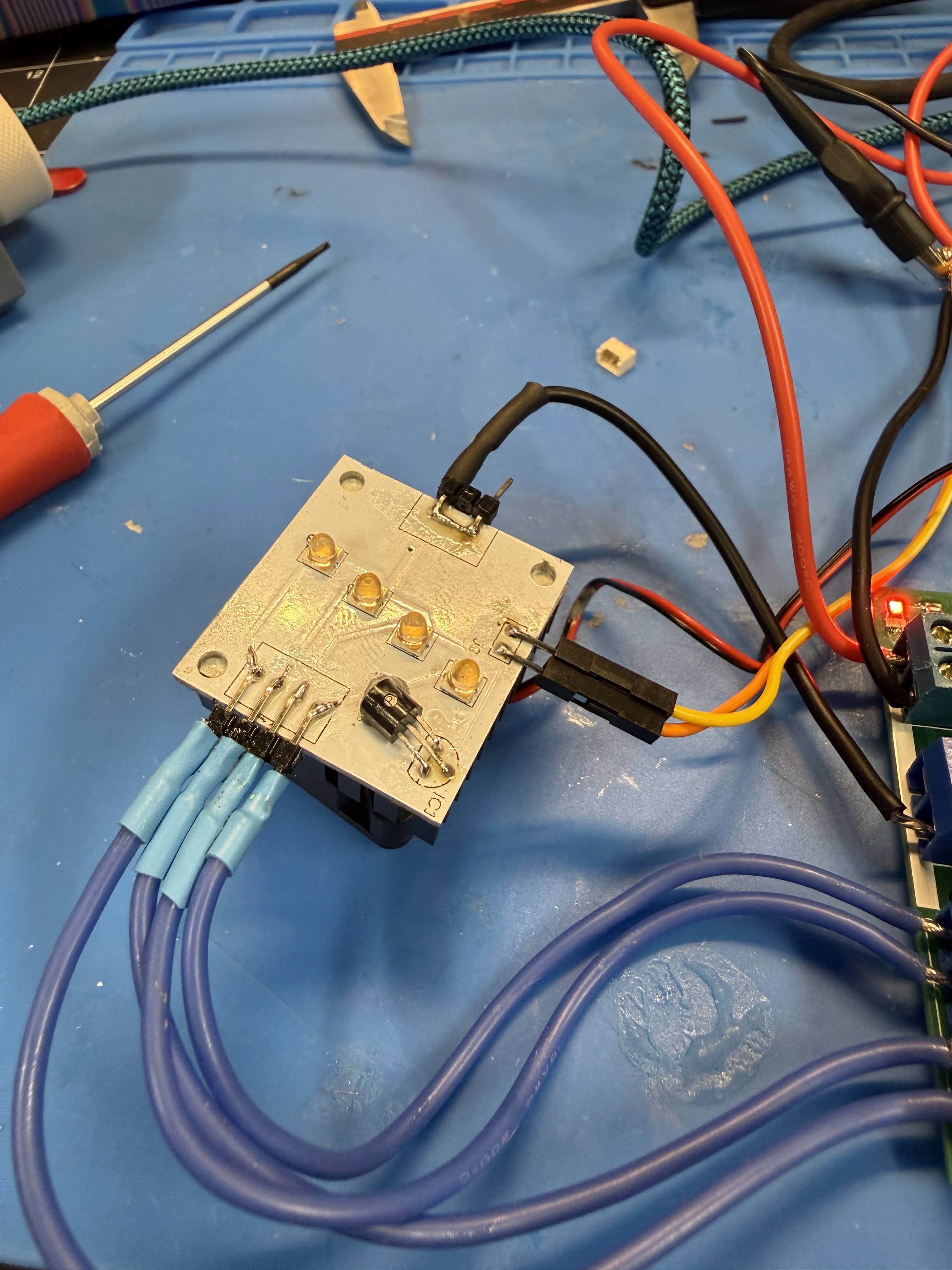
TIER 3: THE PRINTHEAD MCU (Arduino Nano Custom PCB)
- Hardware Attached: 4x UV LEDs (D10-D13), CR Touch (D3 Servo, D7 Signal), 6x TMP36 Temp Sensors (A0-A5), and a NeoPixel Status LED (D8).
- Core Functions: * Operates as a real-time peripheral device (never blocks the UART line).
- Executes microsecond-precise UV exposure timers.
- Manages the CR Touch deployment and background thermal polling.
II. Protocol: Website to ESP32 (The Payload)
The frontend uses a simple, modern REST approach to send the user's design to the ESP32.
1. The HTTP POST Request When the user clicks "Print," the JavaScript fetch API fires a JSON payload to the "/print" ESP32's endpoint.
- Format: JSON
- Structure:
- width (int): The width of the image in pixels.
- height (int): The height of the image in pixels.
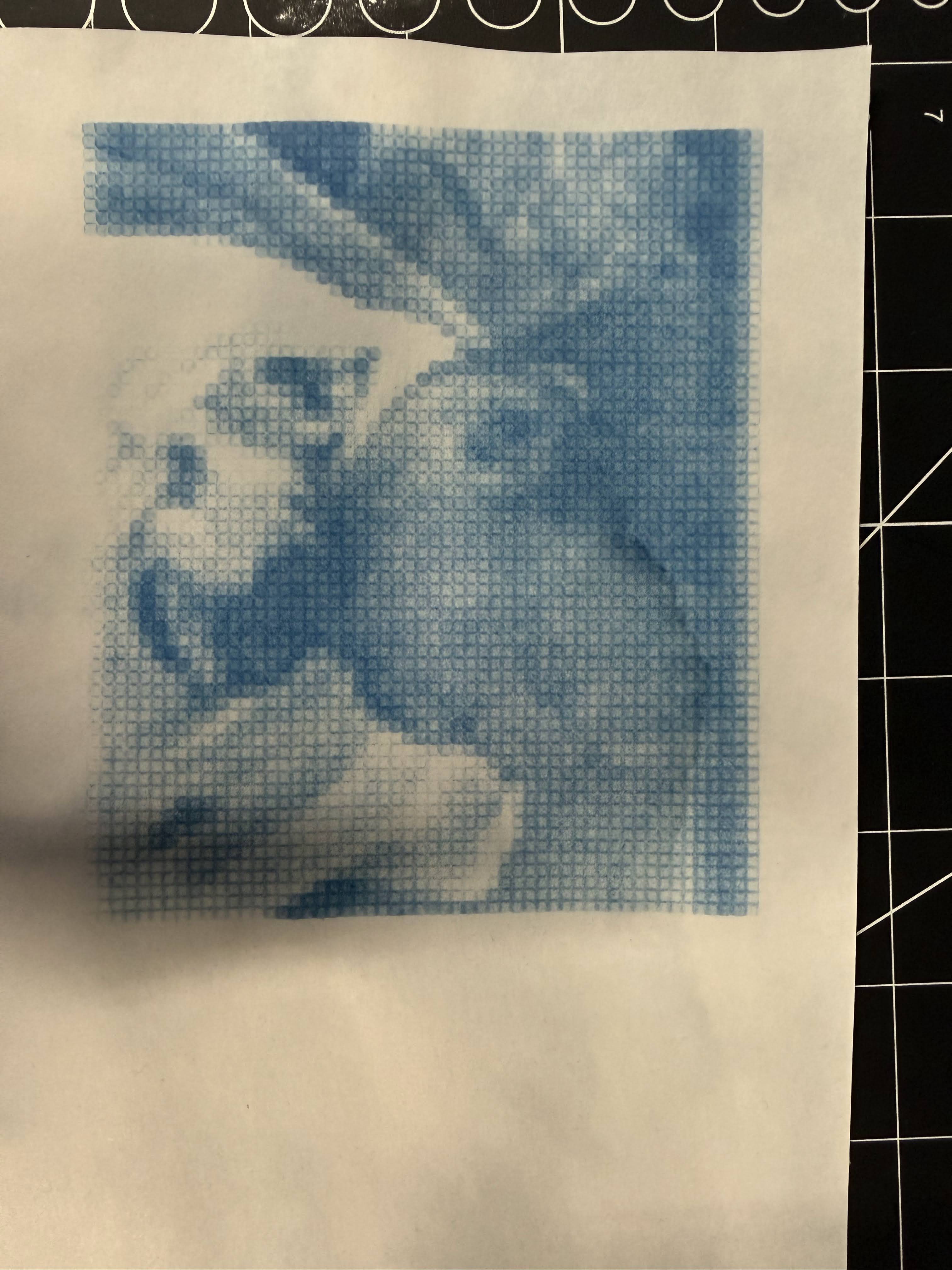
- pixels (array of ints): A flat, 1D array representing the pixel intensities. Each pixel is an integer from 0 (off) to 15 (max intensity).
2. ESP32 to Mega Translation The ESP32 intercepts this JSON, strips out the network overhead, and compresses the pixel array into a single, continuous hexadecimal string to save RAM on the Mega. It sends this over hardware UART.
- Format: P:[width],[height]:[HexData]\n
- Example: P:8,8:000F0000FF00FF00...
- Mechanics: 0 stays 0, 15 becomes F. The Mega reads this string, unpacks the hex characters back into integers, and loads...
 blinkingthing
 Dirk-WIllem van Gulik
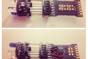
 davedarko
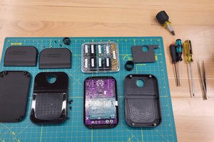
 Supplyframe DesignLab