-
-
-

-
-
Shield wiring diagram
-
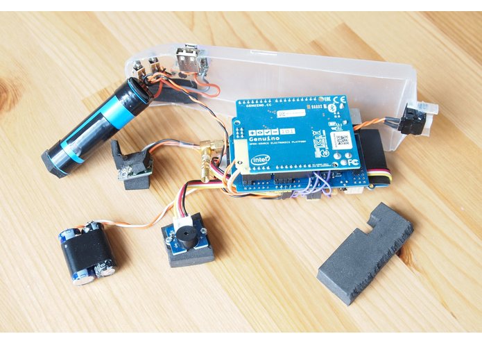
Prototype wiring diagram
-
-
-


Project aim
I wanted to build something with the Arduino 101 that could make a real difference to somebody's day-to-day life. Many vulnerable people have their independence restricted because they are at risk of falling over, or getting lost, when out and about. My device is designed to provide a lifeline to a carer, who will be informed automatically in case they have a problem. In addition, the carer can find out remotely whether the user is OK.
Main functions
The device will send an automatic SMS notification to the carer in the following cases:
- User falls over
- User presses the panic button
- User moves more than a set distance (currently 500m) from the home location
- User's heart rate falls outside set lower and upper limits
- In the response to a query text from the carer
In addition, the following functions are provided:
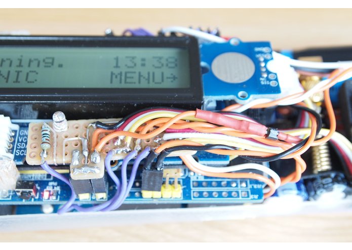
- Text messages from the carer are displayed on the screen
- User can send one of several predefined text messages to the carer
- User can display their GPS coordinates
- User can initiate a heart rate measurement
Parts used
- Arduino/Genuino 101, with built-in IMU and BLE
- GSM shield, to allow sending and receiving of text messages
- GPS module, to get the user's location (also used to determine the current time)
- USB power bank internal parts - an 18650 li-ion cell and power supply/charger board
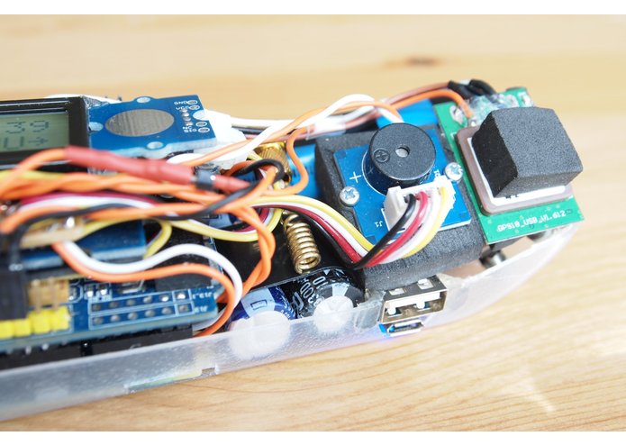
- Grove starter kit parts including the 16x2 LCD with RGB backlight, the touch sensor and the sounder
- A small custom board that connects the parts, in place of the Grove interface shield (to keep the size down)
- Two large electrolytic capacitors to support the peak current drawn by the GSM module when transmitting
- A BLE heart rate monitor (the Bingo M2)
Build details
Initially I built up the device using standard shields (see shield wiring diagram), but I wanted to reduce the size to make the device wearable. I used a small piece of matrix board to replace the Grove interface shield and connect the parts together. Rather than powering the Arduino 101 via the USB input, I connected the 5V supply directly to the 5V pins that connect through the shields. The prototype wiring diagram shows the final result. As you can see, the case is made from a plastic bottle. Well, it is a prototype! The curved shape suits quite well for a wearable device.
Software
I've made the sketch freely available on github, so you can check it out (see below)!
Difficulties encountered
The heart rate monitor I used turned out not to be the best choice. First of all, when wearing the wristband, the heart rate measurement seems to be entirely random, and the same results are given with the bracelet on the table. Secondly, I couldn't find any documentation, and the device does not support the standard BLE heart rate service - it has a proprietary interface. I struggled to get this working, and in the end I could successfully start a heart rate measurement, but was unable to read the results, despite being able to read step counts from the device. The result seems to be generated in a characteristic that is not visible in the initial BLE scan. I'm still a bit stuck with this, so for now the device just assumes a heart rate of 80. I would not recommend this particular heart rate monitor!
Future enhancements
There is a lot of scope for further development. I would like to produce an Android app that automates the remote querying of the device and shows the user location on a map. Also, as the GSM shield is effectively a complete mobile phone, it could allow voice calls to be made, although I would want to keep the interface as simple as possible. Finally, many of the parameters are hard-coded into the software, so some user configuration would be helpful.
Motivation
The device was designed and built for the Intelhacks Devpost Challenge 2017. For full details and a video demo, please see my entry for this challenge!
Built With
- arduino
- ble
- curieble
- curieimu
- genuino
- gsm
- tinygps++

Log in or sign up for Devpost to join the conversation.