-
-
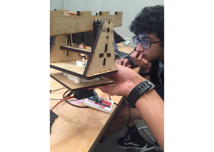
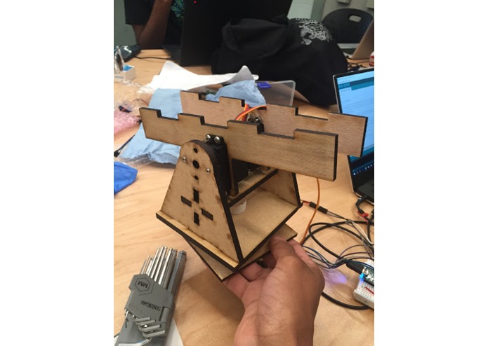
Back view of the frame of Swerve_Cam.
-
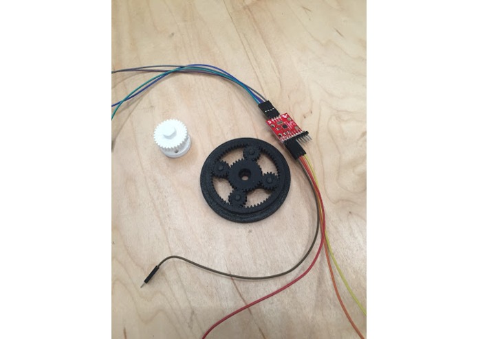
Prototypes of the design (power transfer system, planetary gearbox, gyroscope mounting).
-
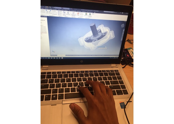
3D model of the planetary gearbox.
-
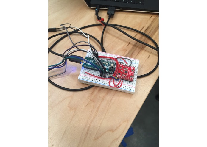
Microcontroller and gyroscope sensor set-up.
-
Front view of the frame of Swerve_Cam.
-
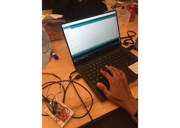
Using ArduinoC to program the servos and read data from the gyroscope sensor.


Inspiration
A significant amount of our team’s technical knowledge and experience stemmed from FIRST robotics. After hearing about NSIN’s challenge at opening ceremonies, we saw a solution that would be fun and feasible for us given our background. Tackling this challenge gave us the chance to reminisce of our highschool robotics days.
What it does
Swerve_Cam uses 2 sets of servo motors to point a camera (or sensor module) in a given direction. A gyroscope mounted to a headpiece dictates the orientation of the camera. We use a microcontroller to read the roll and pitch values of the gyroscope. With these sensor values, we assign an angular position to each of our servos to move the camera into the desired position.
The headpiece allows the user to change the heading camera orientation by moving their head. If the user moves their head up and down or tilts their head left or right, the camera will pan accordingly. This frees up the user’s hands to control the vehicle holding the camera.
How we built it
The overall design of Swerve_Cam is based on a robotics drive train concept called swerve drive. This drive train concept uses one motor to spin the robot’s wheels and another motor to angle the wheel in a given direction. In the same way, we used one set of motors pan the camera vertically and another to rotate the module around.
We used mainly laser-cut wood for the frame of our design and a few 3D printed pieces in lieu of COTS parts we could not get a hold of quick enough. We used a gyroscope sensor mounted to a head-piece to determine the user’s head orientation. To facilitate integration into the vehicle, we added plates with dedicated areas for connecting pieces such as Picatinny mounts.
Challenges we ran into
Our main challenge was the limited hardware resources we had. One example we had was finding a way to create a full 360-degree range of motion with a servo which only turned 180 degrees. No gearboxes we found online seemed to help accomplish this task so we had to design our own.
Another example was the gyroscope sensor. The sensor we used only worked accurately when mounted upright on a flat surface which became an issue with our application We wanted to mount the gyro in a convenient and low profile location. However, due to the inaccuracy of the sensor when mounted vertically, we had to change our approach to controlling the rotation of the camera as well as mounting the sensor.
Accomplishments that we're proud of
One accomplishment we are proud of is having team members apply knowledge outside of their main skill set/major to make useful contributions in the hackathon. For example, we had an electrical engineering major and computer science major work on the mechanical aspects of our hardware project. We were also proud of creating an entirely custom-designed system in both hardware and software.
One specific hardware accomplishment we are proud of is the planetary gearbox. The custom design decreased the height and width of the design as well as allowed a 180-degree servo to rotate the camera 360 degrees with minimal losses in energy and strength of the design.
We are also proud of the overall structure of the design. By using wood with puzzle fits, our frame is both light and durable. Furthermore, we designed each piece so that it could be scaled according to the payload requirements ( larger and heavier camera or smaller and weaker vehicle). By scaling the size of the pieces and swapping out the motors for better-suited ones, our structure can easily adapt to various vehicle and camera specifications.
What we learned
Each of us had a unique learning process while attempting to solve challenges in this project. Some of us became more familiarized with clean design processes and online resources for finding mechanical components. Others familiarized themselves with operating common makerspace tools such as laser cutters and 3D printers for the first time.
What's next for Swerve_Cam
There is no way to determine when an engineering design is “perfect” which leaves a lot of room for improvement through tinkering and adjustment to current designs. Some things we could continue to do to make our design smoother and more effective include integrating better hardware (such as a better gyro for orientation measurements).
We could also add increased structural integrity and decreased weight. With more time, it could be made wireless and a more convenient/comfortable head mount could be created for the breadboard. Adjusting the software to make the translation from head turns to the camera turns more natural could be done as well (this once again could link to better hardware).
Built With
- 3dprinting
- arduino
- arduinoc
- lasercutting
- lsm90s1
- mg996r

Log in or sign up for Devpost to join the conversation.