01
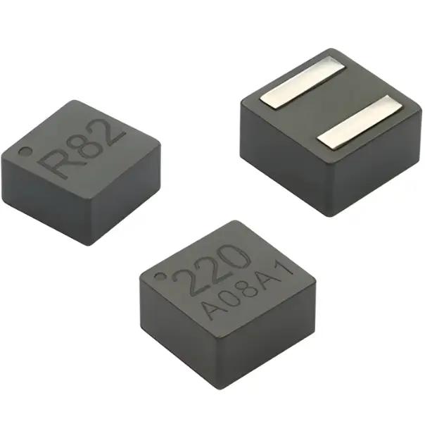
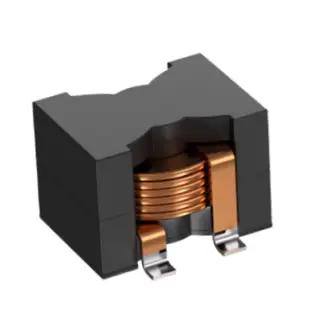
Molded & high current
Compare inductance, DCR, Isat, Irms, package dimensions and datasheets for low-loss, high-current and space-constrained designs.


Engineering · Manufacturing · Support
Coilmx is a power inductor manufacturer specializing in molded power inductors, high-current inductors and common-mode chokes for automotive, industrial power, renewable energy and communications applications.
From material selection and magnetic structure to automated production and reliability testing, we help engineering teams balance package size, DCR, saturation current, temperature rise and cost from prototype through volume production.
For a first selection, define the electrical and mechanical limits before comparing part numbers. Record the target inductance and tolerance, operating current, peak current, switching frequency, allowable temperature rise, available board area and height. These conditions determine whether a catalog part is a reasonable candidate and which datasheet curves need closer review.
Inductance alone does not establish interchangeability. Compare DCR at the stated measurement temperature, saturation current at the manufacturer’s specified inductance-drop threshold, and RMS current at its stated temperature-rise limit. Check that the curves use comparable conditions. Also review package dimensions, recommended land pattern, operating temperature range and any application-specific qualification requirements.
Coilmx product pages provide available model information and datasheet links. Use the cross-reference tool to locate indexed Coilcraft or MPS part numbers, then review the candidate’s complete electrical data. A database match is an initial screening aid; it is not a guarantee that the part will behave identically in every converter topology or operating condition.
Before approving a substitute, evaluate it in the target circuit. Check inductance under DC bias, ripple current, core and copper loss, transient response, temperature rise, acoustic behavior where relevant, and startup or fault conditions. For automotive and other controlled programs, confirm that the exact part and revision meet the project’s qualification, documentation, traceability and change-control requirements.
When requesting engineering assistance, include the original part number, schematic or converter topology, input and output voltage, switching frequency, continuous and peak current, thermal limits, package constraints and expected annual volume. Providing the datasheet and test conditions helps the engineering team distinguish a close parameter match from a part that still needs a design review or sample evaluation.
The product catalog is organized by inductor family and series so that engineers can move from an application need to the relevant specifications and model pages. Start with the family that fits the required construction, compare series-level ranges, and open individual models for detailed parameters, dimensions and downloadable technical documents. Contact the team when the available data does not answer a project-specific question.
Molded power inductors are commonly considered where a compact surface-mount component and a molded magnetic body fit the design constraints. The suitable choice still depends on the converter’s ripple current, bias point, thermal path, switching frequency and board layout. Compare the model’s published electrical curves with the actual operating range instead of choosing by package size or nominal inductance alone.
High-current designs also require attention to conduction loss and thermal margin. A lower DCR can reduce winding loss, but the complete design must account for copper area, airflow, nearby heat sources and the temperature at which current ratings were measured. If the inductor operates near a limit, bench measurements in the intended assembly can reveal differences that a headline rating does not show.
For a cross-reference review, treat the competitor number as a search key rather than an approval. Confirm the matched Coilmx model, datasheet revision, electrical limits, dimensions and mounting pattern. Then compare the expected operating point against both datasheets and run the required prototype tests. If no indexed match appears, submit the part number and design requirements for a manual review instead of assuming that a similar-looking package is interchangeable.
The catalog and engineering resources are intended to support that review process: browse a product family, compare available series and models, consult technical notes, and contact the team with the operating conditions that matter to the application. This gives engineers a practical starting point for evaluating a power inductor manufacturer and its products while keeping final selection tied to documented specifications and circuit validation.
Common-mode chokes serve a different purpose from power inductors, even when both appear in the same product catalog. They are selected for their impedance behavior and noise suppression across the relevant frequency range, while the winding configuration, current rating, insulation needs and PCB implementation depend on the circuit. Review the intended signal or power path and the manufacturer’s test setup before comparing a choke by its headline impedance value.
Thermal validation should reflect the finished assembly. Copper thickness, pad geometry, neighboring components, enclosure temperature and airflow can all affect the measured result. Record the test board, ambient temperature, load profile and measurement location so that prototype comparisons are repeatable. If a design change alters the layout or operating point, repeat the relevant checks rather than carrying an earlier result forward without review.
Documentation is part of a reliable component decision. Keep the selected datasheet revision, electrical comparison, footprint review, sample test results and any customer-specific qualification records with the project. For controlled supply programs, confirm ordering information and change-notification expectations with the supplier. These steps help purchasing, quality and design teams work from the same approved part definition when a project moves from evaluation to production.
Engineering snapshot
Compare inductance, DCR, Isat, Irms, package dimensions and datasheets for low-loss, high-current and space-constrained designs.
Support for AEC-Q200 qualified inductors, PPAP documentation, traceability and project-specific reliability or validation requirements.
Identify possible alternatives to selected Coilcraft and MPS part numbers, then review bias, frequency, thermal and package conditions before qualification.
Share operating current, switching frequency, thermal limits, package constraints and supply goals for standard or custom inductor recommendations.
Global Professional Inductor Manufacturer
Explore product series, technical specifications and engineering support for component selection
Years Experience
Product Models
Quality Rate
Countries Served
Customers Worldwide
Complete R&D production line with full control from raw materials to finished products
International advanced automation equipment ensuring consistency and efficiency
ISO9001, IATF16949, AEC-Q200 and other international certifications
Professional team providing 7x24 global technical support
Coilmx's proprietary online design tools help you quickly complete your selection. We provide comprehensive design tool services to accelerate your design journey.
Experience NowLatest technology product news and company updates, providing you with full technical support and industry insight.
One-stop inductor solutions for global customers
Comprehensive resource center including catalogs, manual downloads, and technical notes.
Maintained by: Coilmx · Updated
Start with the inductance range recommended in the power IC datasheet, then check peak current, RMS current, DCR, temperature rise, dimensions and switching frequency. Compare the inductance-drop threshold used for Isat and the temperature-rise condition used for Irms. Nominal inductance or a headline current rating alone cannot establish suitability. Validate the candidate on the target PCB under actual cooling conditions.
For an initial continuous-conduction-mode estimate, the TI buck power-stage application note gives 20%–40% of output current as an estimated ripple-current range. At 5 A output and 30% ripple, peak-to-peak ripple is approximately 1.5 A and peak inductor current is approximately 5.75 A. This is a calculation example, not a product rating. Follow the IC recommendations and check transients, current limiting and saturation margin.
A cross-reference result is a candidate for review, not approval for substitution. Compare inductance and tolerance, DCR, DC-bias curves, Isat, Irms, package dimensions and land patterns under equivalent test conditions. Check temperature rise, ripple, startup and fault behavior in the target circuit. If the original part is not indexed, submit its datasheet and design requirements for a manual review.
Provide the target part number or original datasheet, input and output voltages, continuous and peak current, switching frequency, target inductance, package-height limits and thermal limits. Include the converter topology, sample quantity, expected production needs and required quality documentation where available. These details help assess a standard or custom candidate and identify which validation conditions still need clarification.
Review AEC-Q200 test documentation for the exact part and revision, the operating temperature range, traceability requirements and the customer approval process. A company quality-system certificate does not establish qualification for every product. Before production approval, confirm applicable reliability records, PPAP documentation, change-notification requirements and validation results for the intended application with the supplier.
Working hand in hand with excellent global industry platforms and Web Directories to provide a higher quality experience.