Close
0%
0%

Rocket Payload

Electronic Payload to record and display flight data for model rocket.

Similar projects worth following
A small lightweight PCB that can be inserted into the payload section of a model rocket to record altitude, g-force and rotation during flight. The data is uploaded to an application which displays the resulting flight parameters.

I'm not a rocket enthusiast, but I belong to a radio control club which has members who are. You can purchase commercial versions of this Payload, but I think this one is smaller and lighter weight than most others and will be much less expensive (if you don't count my labor.)

Disclaimer:

I'm using Anthropic's Claude Code to aid in writing both the firmware and application software. Without Claude this project would either: be much longer, if I had the ambition, or would not exist due to my lack of knowledge on the software side of it.

Two Payload Versions:

A "STANDARD" version with less data storage (512kb EEPROM). Records the flight parameters:

  • Max thrust
  • Burn duration
  • Maximum Altitude
  • Time to apogee
  • Recovery time.
  • Total flight time.

Real time sensor readings (barometer, accelerometer, gyro, temperature) at user selected intervals (20ms, 40ms, 80ms, 160ms) from launch detection to 5 seconds after apogee (or up to max interval set by user), then records data during recovery at 1 second intervals until landing.

A "PRO" version that has 4Mb of EEPROM. Has storage for up to 8 flights. Records the flight parameters above and the real time sensor readings from launch detection to 5 seconds after apogee (or up to max interval set by user), then records data during recovery at 1 second intervals until landing.

What it Does:

  • Uses a 1S 501010 LiPo battery -- 40mAh, 5mm x 10mm x 10mm, weight: 1g.
  • Sensors: BMP384/BMP390/BMP388 for altitude (pressure), LSM6DSO32 IMU for g-force (accelerometer) and rotation (gyro)
  • Payload can be inserted completely into payload section of rocket and "armed" by placing strong magnet along side of rocket.
  • Payload confirms arming and beeps every 5 seconds while armed. Ready for launch 5 seconds after arming.
  • Rocket launch axis automatically determined when armed. Launch is detected by exceeding user specified g-force along the launch axis. Sensors sample at user selected sample rate (50Hz max.) intervals.
  • After launch is detected the Payload saves the flight parameters and the flight history to EEPROM.
  • After apogee + 5 seconds (or maximum fast sample duration), sensors switch to sampling at 1 second intervals.
  • Landing detected after 5 seconds of unchanging altitude. 
  • Upon landing, Payload goes to sleep while emitting a beep every 5 seconds.
  • User recovers rocket and Payload. Then disarms payload with magnet. Payload stops beeping and enters true sleep mode -- 17μA.
  • The battery can be removed at this point. The data is stored in non-volatile memory.
  • Data is extracted when user connects Payload to USB interface and uploads data to application that displays the flight parameters/history.

Specifications:

  • Supply Voltage Range: 4.2V - 3.3V (pretty much the useful voltage of a 1S (3.7V) LiPo battery.)
  • Dimensions: 15mm x 40mm x 8-9mm, including battery and enclosure.
  • Weight: around 5g, including battery and 3D printed enclosure.
  • Runtime from 501010 battery: TBD, but should be greater than 1 hour in launch mode. Estimated max supply current < 10mA.
  • Sleep/standby Duration: 50 days from fresh battery. 17μA.
  • Acceleration Measurement: ±32g max, resolution 1mg.
  • Gyro Measurement: up to 2000 dps full scale, TBD resolution.
  • Pressure Measurement: 
    • Max altitude -- 27,000m/88.5k feet (300 Pa)
    • Relative Accuracy -- ±0.75m (0.09 hPa)
    • Resolution: ~ 1mm (0.016 Pa)
  • Fast Data Record Length: 72 seconds maximum at 50Hz.
  • Recovery Record Length: depends upon user selection of fast sample duration.
  • On-board 1S battery charger: 20mA, ~ 2 hour charge time from fully depleted to fully charged. Charges when connected to USB.
  • USB data transfer: 76800 baud UART, duplex.
  • Cost for components and PCB: Around $30 for the STANDARD version, $33 for the PRO version.

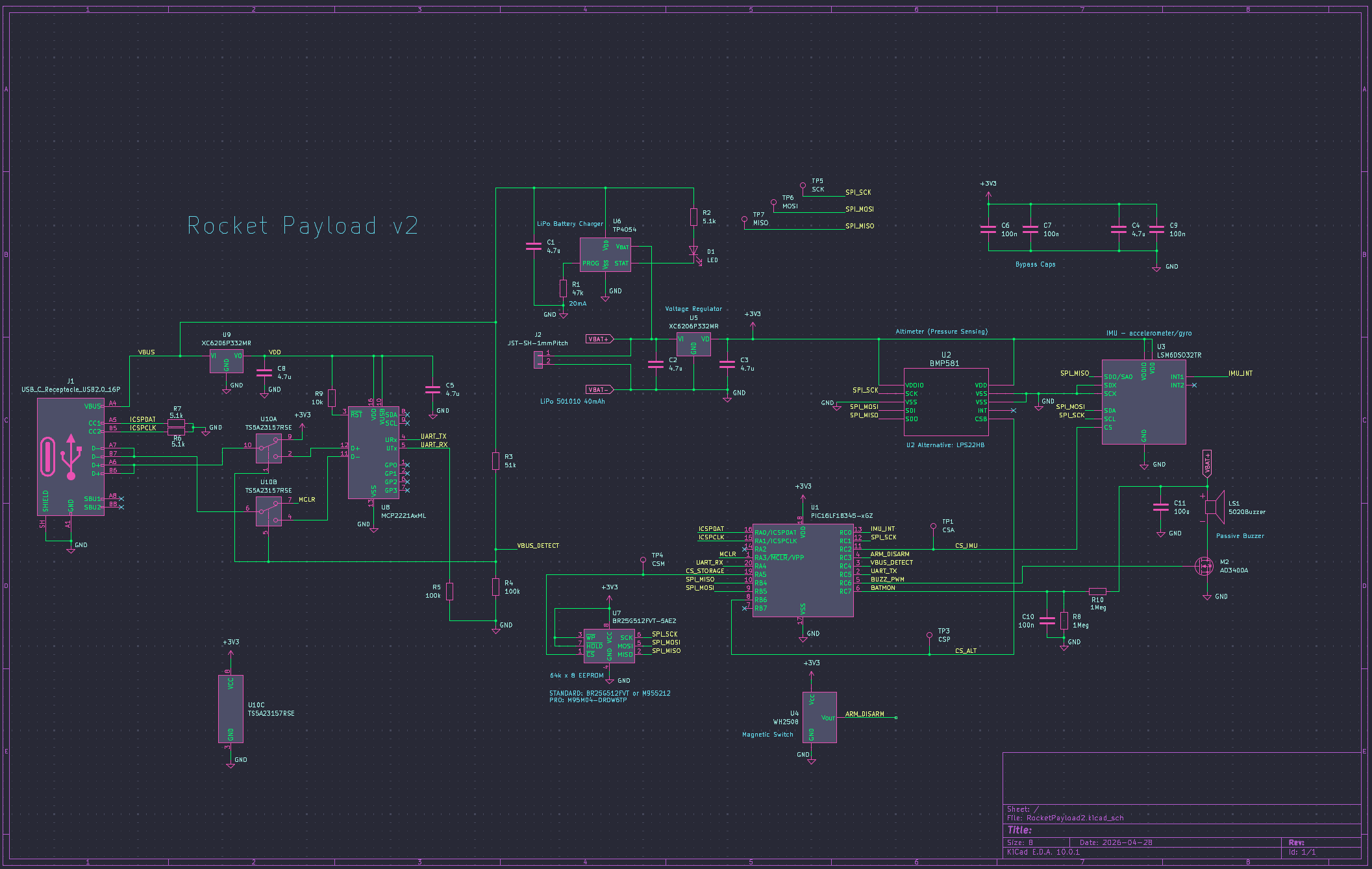
Latest Schematic (v2) [as of 2026-07-06]:
Image

Image

It is surprisingly simple, given the complexity of operation. Claude and I chose a PIC16LF18345 for the micro-controller. I have a PICKit4 programmer that keeps me in the Microchip camp for now. The PIC has about...

Read more »
  • 1 × LSM6DSO32 IMU -- Inertial Module includes accelerometer and gyrometer
  • 1 × BMP581 or LPS22HB Pressure Sensor for Altitude
  • 1 × PIC16LF18345 or PIC16F18346 8-bit PIC micro-controller
  • 1 × WH2508 Hall-effect switch
  • 1 × MCP2221a USB-UART controller

  • Fixed?

    Bud Bennett8 hours ago 0 comments

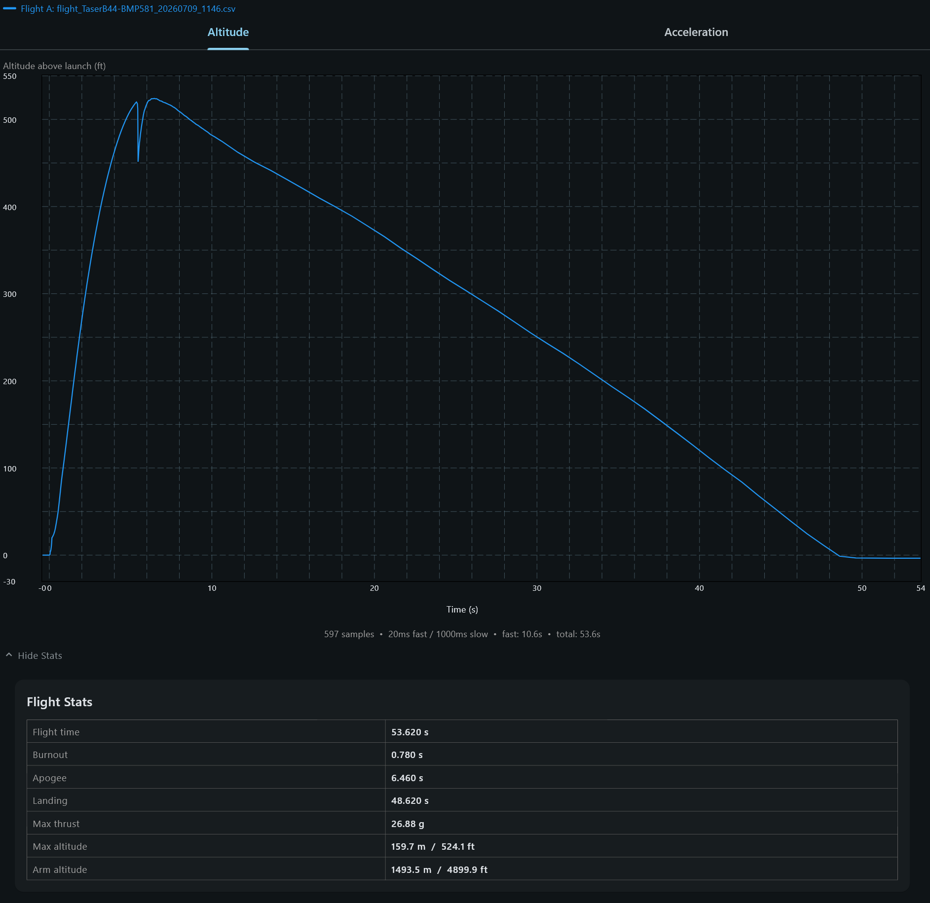
    I recorded another Taser flight with a B4-4 engine. Similar performance to the previous flight, but without the missing 200ms of data at launch:

    Image

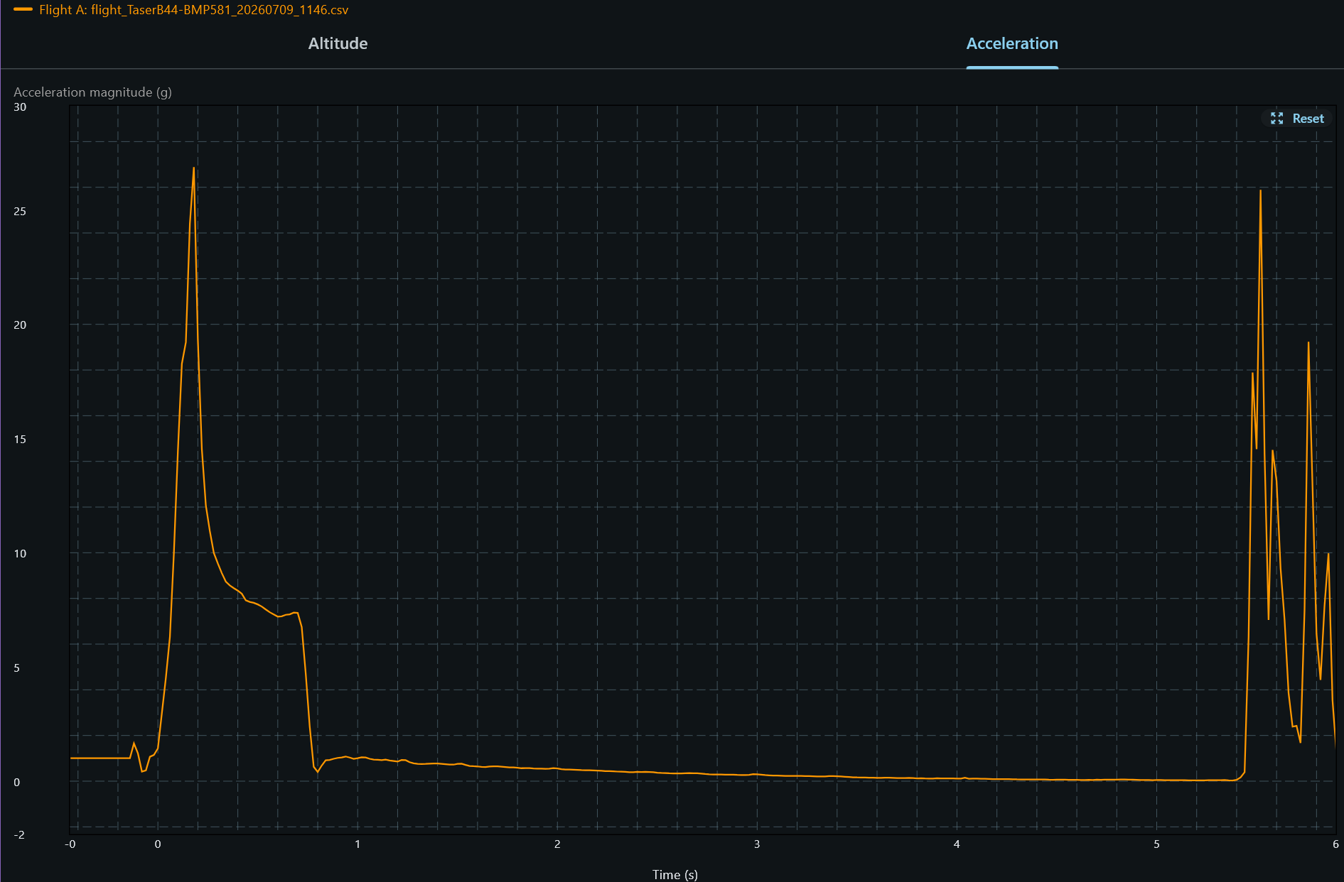
    The acceleration data shows a much more believable trace:

    Image

    Note that the burnout didn't occur until nearly 0.8s, and there is no longer a discontinuity in the accel or altitude data. There is a bit of wiggle in the acceleration data prior to launch. This caused the app to generate erroneous values for the Flight Stats. The algorithm now resets if the acceleration drops below g=1.0, and uses g > 1.3g to establish true launch event. All of the Flight Stats are now based upon the "true launch event time" rather than the launch detection threshold set by the Settings.

    This should yield a better correlation between actual data and the simulation results from OpenRocket.

  • Lost Time

    Bud Bennett07/06/2026 at 18:30 0 comments

    The 500ms B4-4 engine burn duration explained:

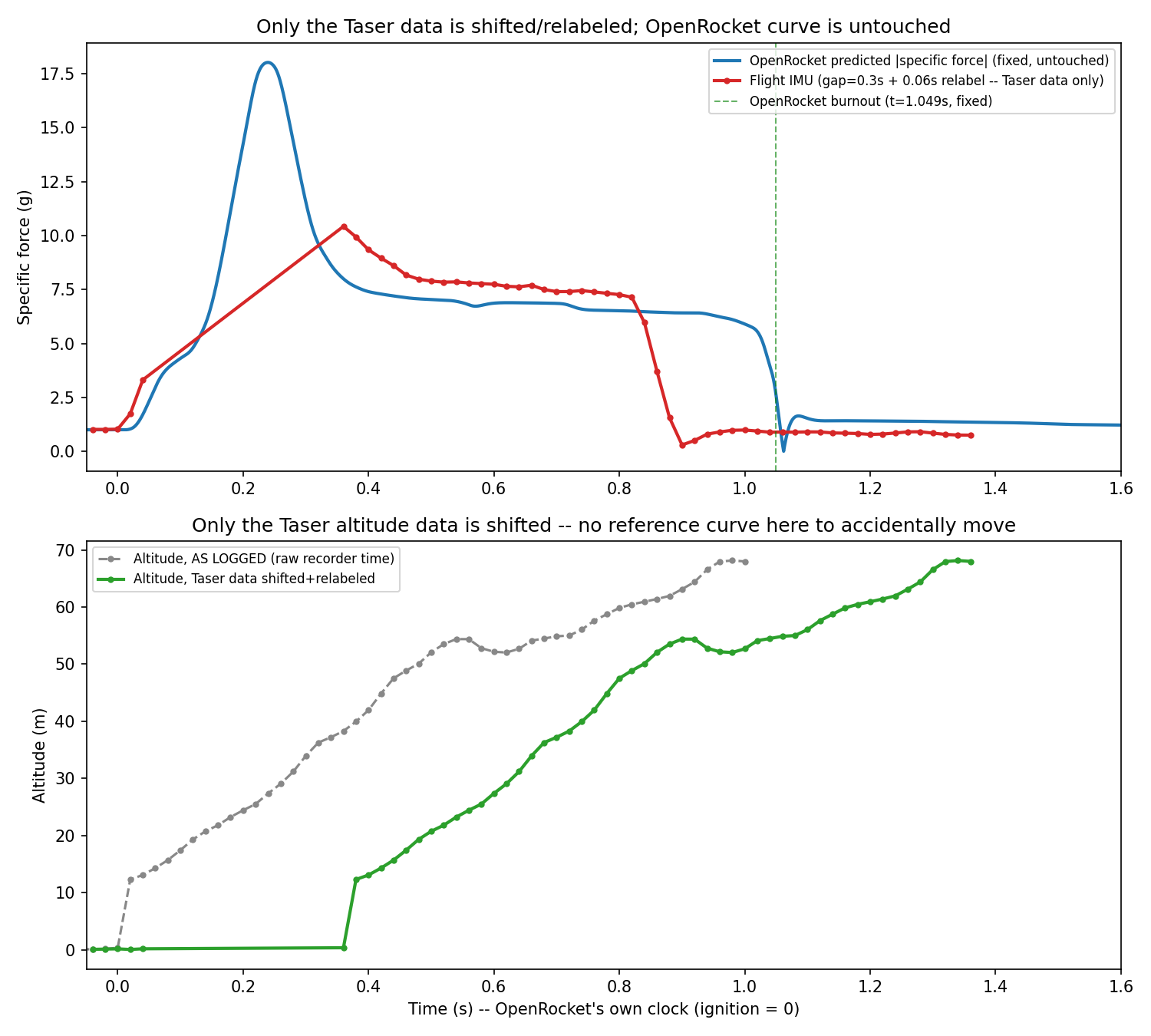
    I couldn't explain why the Taser rocket flight had such a short burnout duration, but still achieved a remarkably high altitude. I decided to pursue it a bit further (actually quite a bit further) and installed OpenRocket on my PC and proceeded to model the Taser to a first-order correctness. OpenRocket presented a much longer B4-4 thrust duration than what I got from the acceleration data.

    After a lot of back-and-forth with me yelling at Claude about how stupid he is, we finally came up with a reasonable explanation about what could be happening to the data -- it was missing.

    Here is Claude's plot of the corrected timeline, after adding roughly 300ms after the launch was detected by the Payload:

    Image

    The final piece of the puzzle was to find the intersection of the altitude slope after launch with y=0. Claude used a much more sophisticated approach (he did not like my 'eyeballing' the data.) 

    I took this conjecture back to Claude Code, who is responsible for the firmware code, and asked him how this could be. After a few minutes of "noodling" he presented a list of culprits -- mostly blocking by the buzzer. I had asked for a short chirp from the buzzer when the launch was detected -- this helped with debugging early on. Also, the 5s heartbeat chirp could interfere with data sampling immediately after launch if it occurred just prior. And lastly, the ring buffer that collects 500ms of data prior to launch was causing a delay while writing to the EEPROM. These totaled to 150-300ms.

    These were mostly easy fixes: Eliminate the beep at launch (no longer needed), keep the ring buffer in RAM until after landing when there is plenty of time to write it to the EEPROM, and prevent the heartbeat chirp from blocking data sampling. All of these changes were implemented (saving a bit of program memory.) All is well.

  • BMP581 Pressure Sensor

    Bud Bennett06/24/2026 at 03:32 0 comments

    I don't know why it took me so long to discover the BMP581. It is seemingly superior in almost every way to the others that I've considered: BMP384, BMP388, BMP390, LPS22HB. Like the LPS22HB, the BMP581 outputs temperature corrected pressure data, saving the PIC quite a few lines of code in order for it to detect apogee and landing. It also has a metal can with very tiny port holes, which I find easier to solder without getting gooey flux on the package. All of these sensor have identical footprints and pinouts, so I did not have to modify the PCB.

    The SPI protocols are different so I must have a separate file for each sensor when compiling. Claude and I found out that the first SPI transmission after POR or soft reset must be a dummy read because the BMP581 determines which interface to configure based upon that first transition of chip select. The datasheet suggests to send a dummy read, then a soft reset, but doesn't say to send another dummy read after the soft reset.

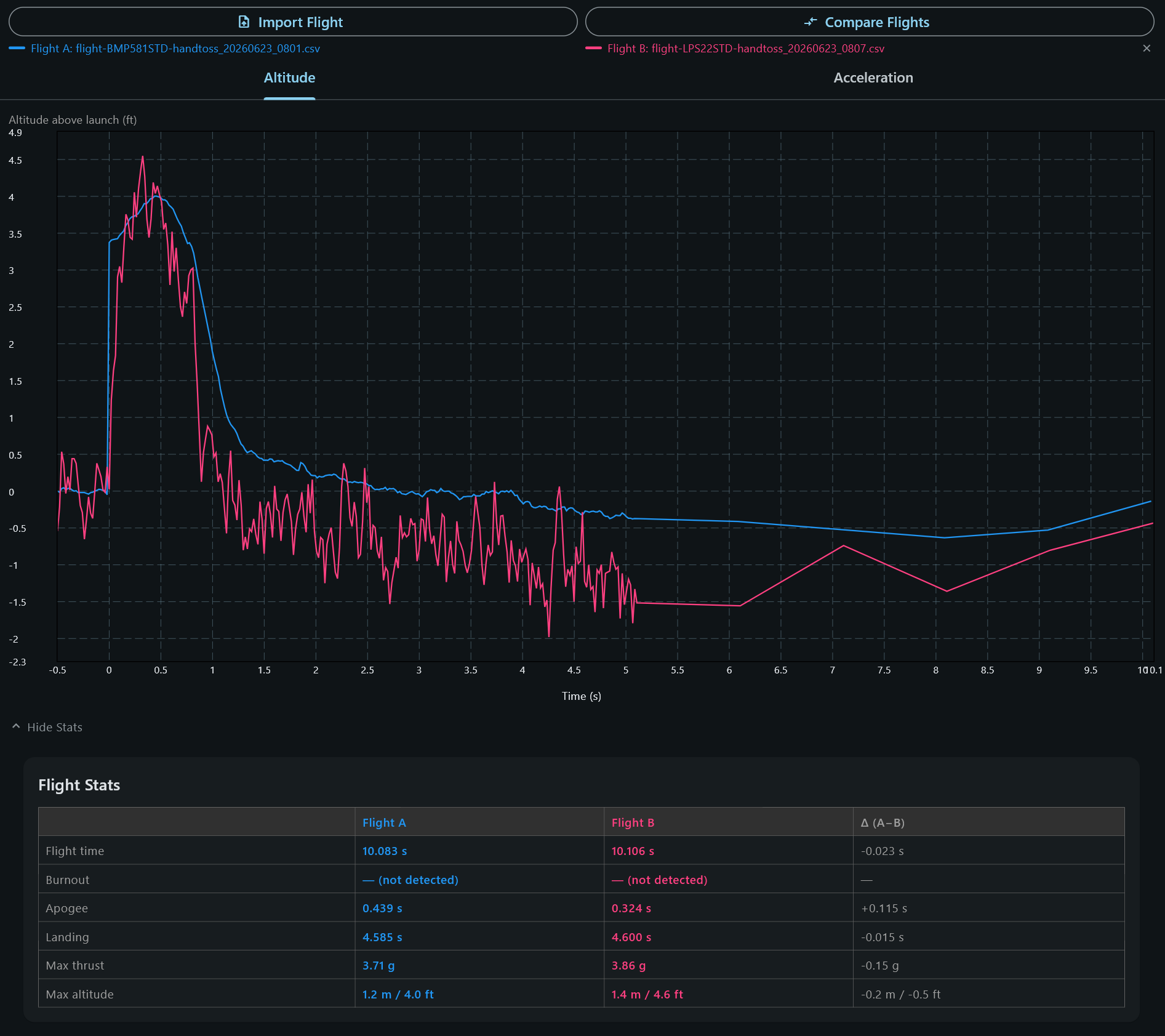
    But here's a comparison between the LPS22HB (pink) and the BMP581 (blue):

    Image

    The BMP wins on noise level and response time. I'll be using the BMP from now on.

  • First v2.0 Flight Data

    Bud Bennett06/20/2026 at 16:57 0 comments

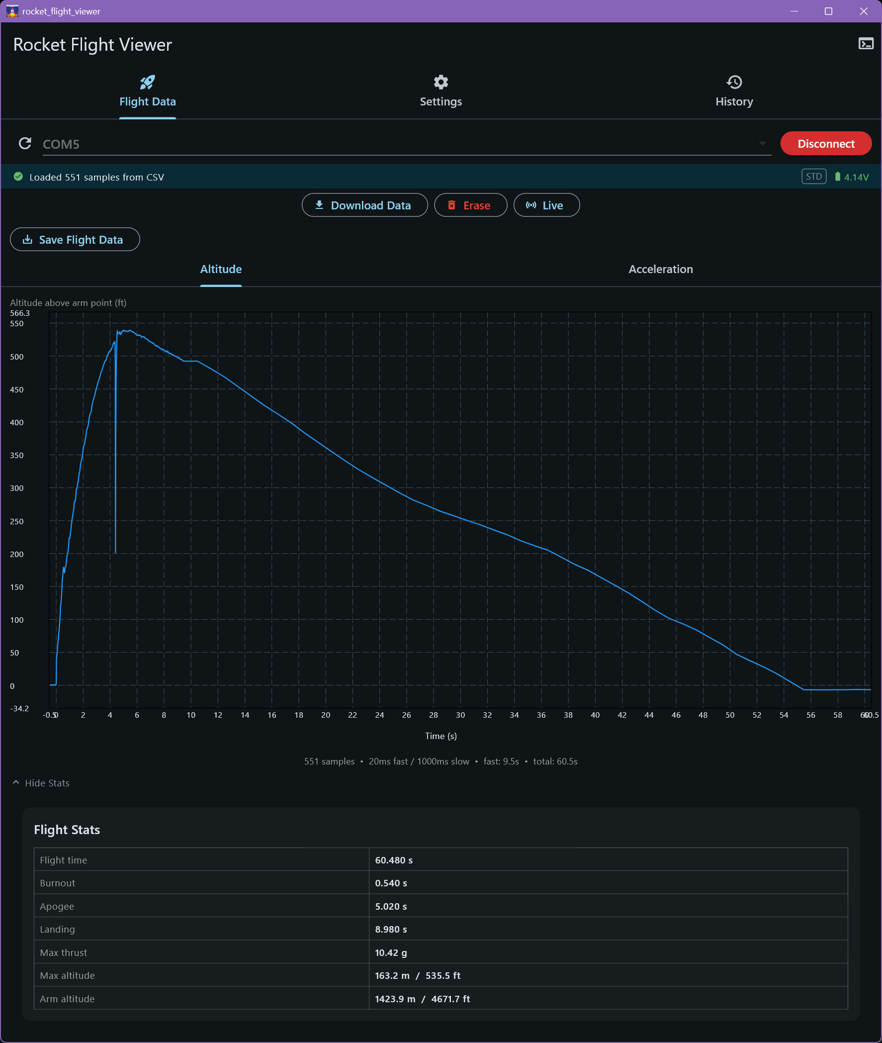
    I bought a cheap Estes launch kit for $22. It included the launch pad, ignition box and a simple kit called the Tazer. The Tazer is 17 inches (43.2cm) long with a 1 inch (25mm) diameter. I also purchased a few rocket motors (B-4-4 and B-6-4) and wadding. After building the rocket I drilled 3 1/16" (1.5mm) holes to vent the body were the payload would reside. There is no payload section so I folded the chute, attached the payload to the cleat at the bottom of the nose cone, and shoved the payload into the space between the cone and the chute. Launch day winds were light -- 2-5mph -- so I launched it true vertical. I pushed the button on the ignition box and lost sight of it immediately, wondering where it was until I heard the chute deploy and caught site of the parachute. It drifted about 500 feet from the launch site. I disarmed it upon recovery. Here's the page of the app showing the plot of altitude and the flight stats:

    Image

    I expected that big discontinuity when the chute deployed (a bit early), but the pressure sensor recovered very quickly. Quickly enough that you can easily interpolate from the missing data. I also expected there to be a large step function when the Payload was ejected into ambient air. That didn't happen, which leads me to believe that the three small vent holes are adequate to allow reasonable tracking of pressure or altitude. Note also that there is a bit of a jog at burnout -- I did not expect that to be visible in the altitude data. 

    That flat spot at the transition from fast sampling to slow sampling looks like a bug. I think the Payload substituted the last fast sample data for the first slow sample data point. I'll take that issue up with Claude.

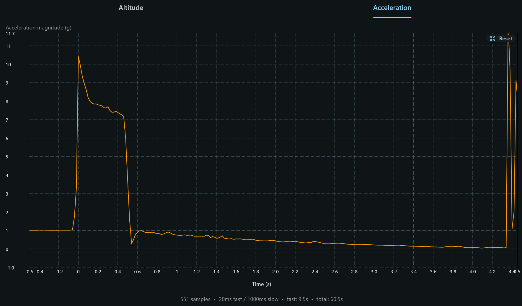
    Acceleration Data:

    I zoomed the data to just reflect the time from launch until chute deploy.

    Image

    This looks to be first-order correct. The launch threshold was set for 3 samples above 3g (2g + 1g). That would be the 0 second point on the plot. So the actual ignition occurs in negative time, which the Payload captures. 

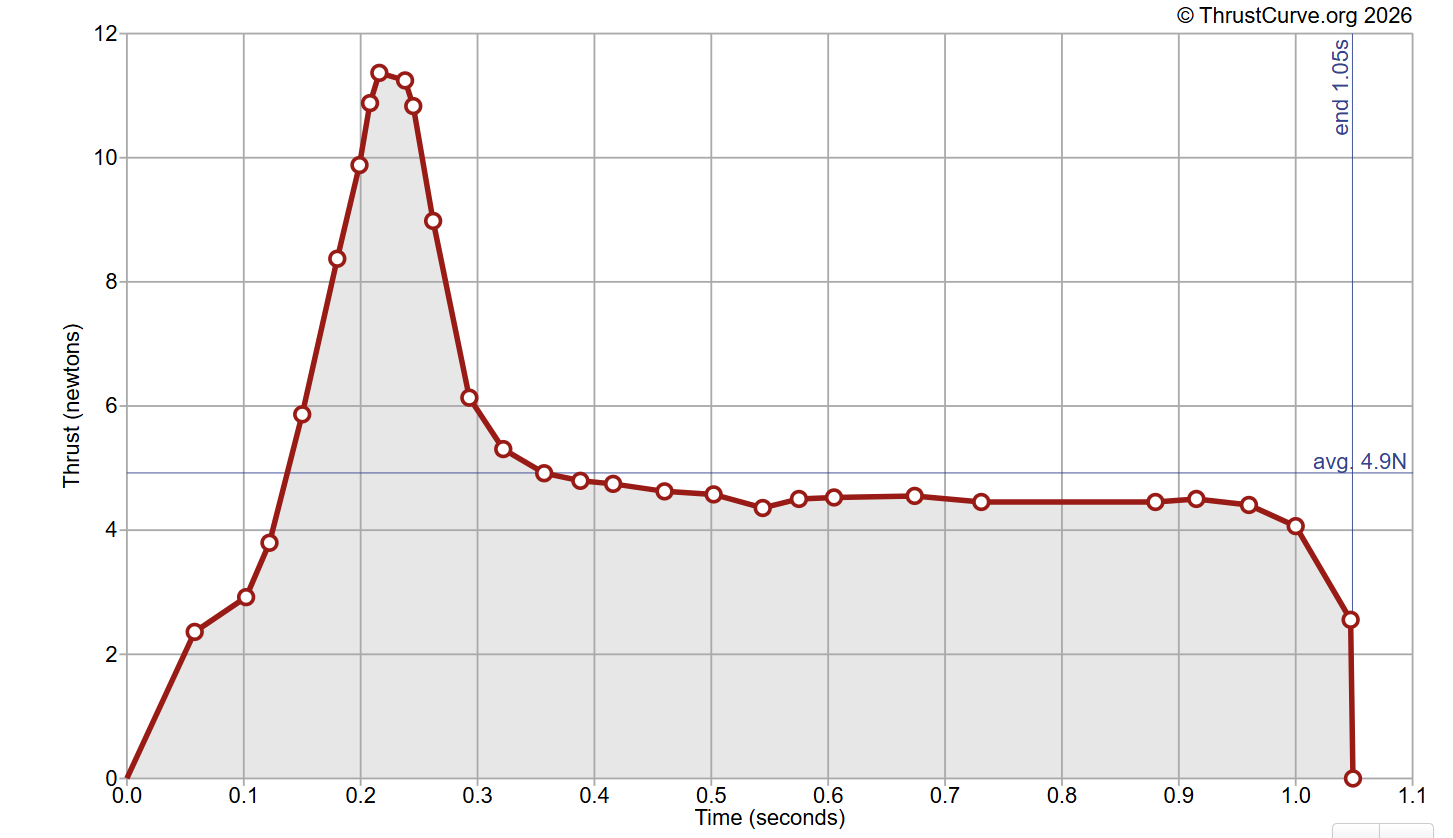
    I found the thrust curve of a B4 motor at ThrustCurve.org:

    Image

    This shows the same impulse spike, though not as sharp, with a 2X longer burn time than what I get -- Payload data shows burnout occurred at 0.54s. Time from launch to deploy was nearly 4.5 seconds, so the delay is spot on.

    I expected the rocket to enter free fall (zero gravity) earlier, but a rocket flight is not like a hand toss.

    Summary:

    Very good data for a first attempt. There is one issue to fix, but generally proves that recording method is sound. A B6-6 might be a good match for this Tazer model to get more height.

  • Version 2

    Bud Bennett06/06/2026 at 21:14 0 comments

    v2.0 Prototypes:

    I sent Claude to canvas the available collection of hobbyist model rocket flight recorders and make recommendations for upgraded features. He came back with two suggestions:

    1. Integrate the USB interface with a controller that doesn't require Windoze to install a special driver. This would spare the user additional expense of purchasing the CP2102 adapter and the custom wire harness. A simple USB type-C terminated cable is all that is required to connect and download flight data.
    2. Add a (PRO) version that will allow the user to record multiple flights without having to connect a USB port for downloading data.
    3. Increase the baud rate of the USB connection from 9600 to 76800. This will reduce the time required to download multiple flight data.

    With these upgrades the Payload would be competitive with all of the sub-$125 offerings: Many don't include an accelerometer. None of them offer an exhaustive multi-OS interface -- usually one or two at most -- and some don't offer downloading data. Many require the user to purchase an external battery charging module at additional cost. As far as I can tell, the only feature this Payload lacks is a Bluetooth connection primarily for interfacing to an iPhone.

    v2 changes from v1:

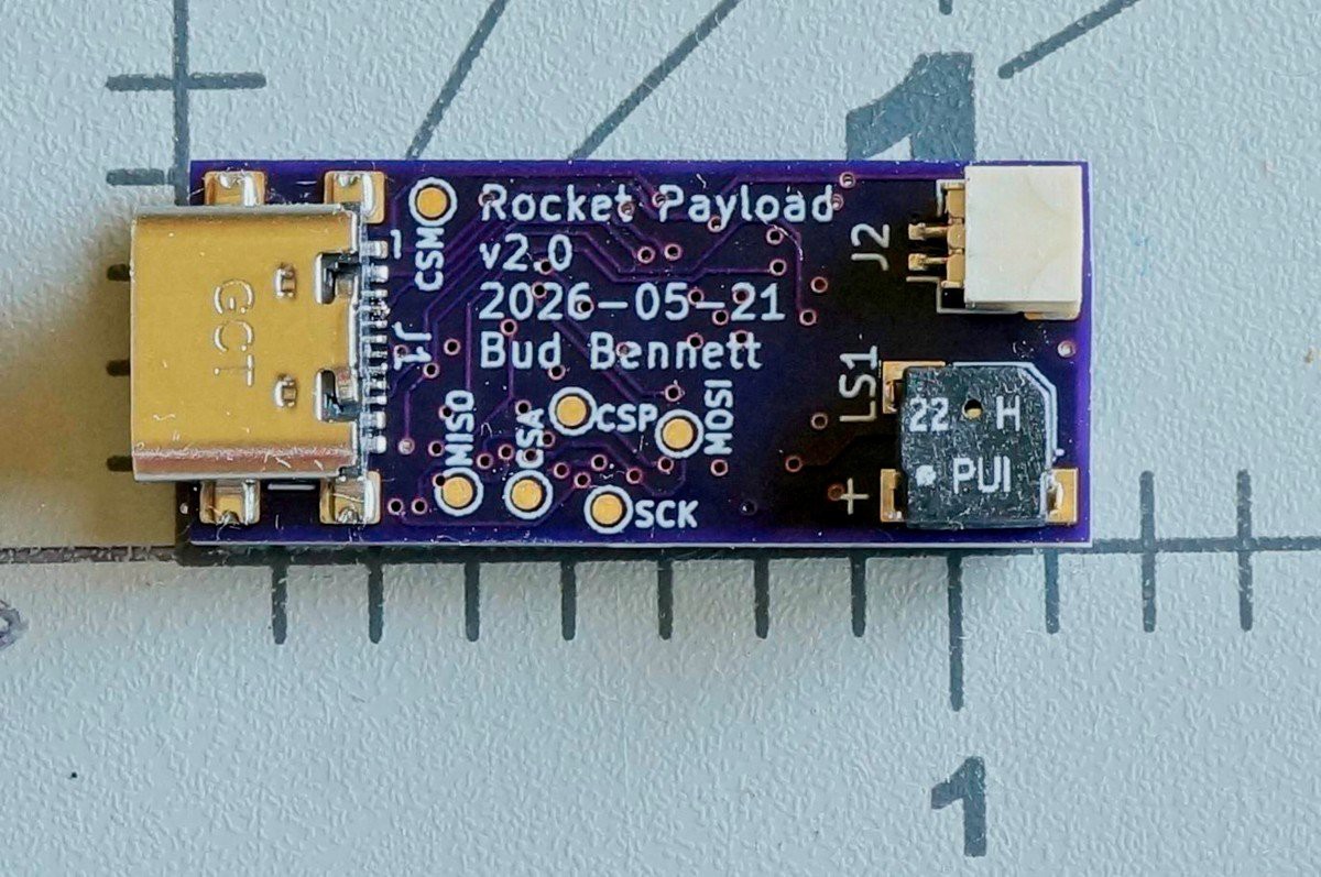
    • Added the MCP2221a USB-UART "Protocol Converter" to eliminate the outboard CP2102 adapter. The MCP2221a doesn't require a special windows driver installation, which is a plus, but time will tell. The MCP2221a requires its own 3V3 LDO (another XC6206) -- it only regulates the supply for the USB signals so the UART outputs have 5V logic levels, which would overdrive the PIC. There is a USB connector mounted on the back side of the PCB. It is compatible with USB 2.0 -- requiring a 16-pin connector.
    • Figuring out how to program the PIC was a challenge. There is no room on the PCB for any kind of pin header, or even POGO pins. I eventually figured out that I could use the USB connector interface to program the PIC by inserting a SPDT analog switch. The switch routes VDD (3V3) and MCLR to the USB connector when VBUS is not present (0V). Otherwise (when VBUS=5V) those pins are connected to D+/D- between the USB connector and the MCP2221a. The PIC programming pins, ICSPDAT/ICSPCLK, are dedicated to the CC1/CC2 pins of the USB connector. During normal operation CC1/CC2 just have a 5.1k resistor connected to GND, which is a low voltage. As of right now this concept has not been tested.
    • I recently discovered the ST LPS22HB pressure sensor. It has an identical pinout/footprint to the Bosch series of pressure sensors (BMP390, BMP384, BMP388). The advantage is that the LPS part calculates temp compensated pressure, which avoids having the PIC perform that task without floating point math. It also is stocked in large quantities (~10k) at JLCPCB/LCSB and I can get prototype quantities from Digikey.
    • Added a battery monitor feature. The App will display battery voltage as it is being charged. There is also an LED indicator. The plan is to warn the user when the battery drops below 3.5V as he arms the Payload for a flight.
    • The PRO version will have a 4Mb EEPROM and be able to store 8 flights (maybe more.) As of now, each flight will occupy 512kb of memory. If the user doesn't download the flights before the 8th flight, the oldest flight gets overwritten. The flight count is indicated when the payload is armed -- every 5 seconds the current flight count is beeped out by the buzzer as a rapid burst.
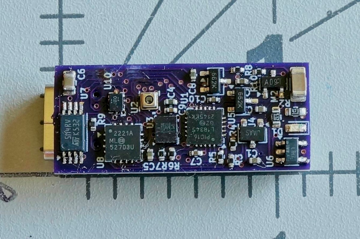
    • The PCB was upgraded to 4-layer. It is still the same dimensions as v1 -- 12.48mm x 29.35mm. Most of the passive components were changed to 0402 size (which are a PITA to solder.)

    All of this was incorporated into the same dimension PCB:

    Image
    Image

  • Version 1 Prototypes

    Bud Bennett06/06/2026 at 19:46 0 comments

    v1.1 Prototypes:

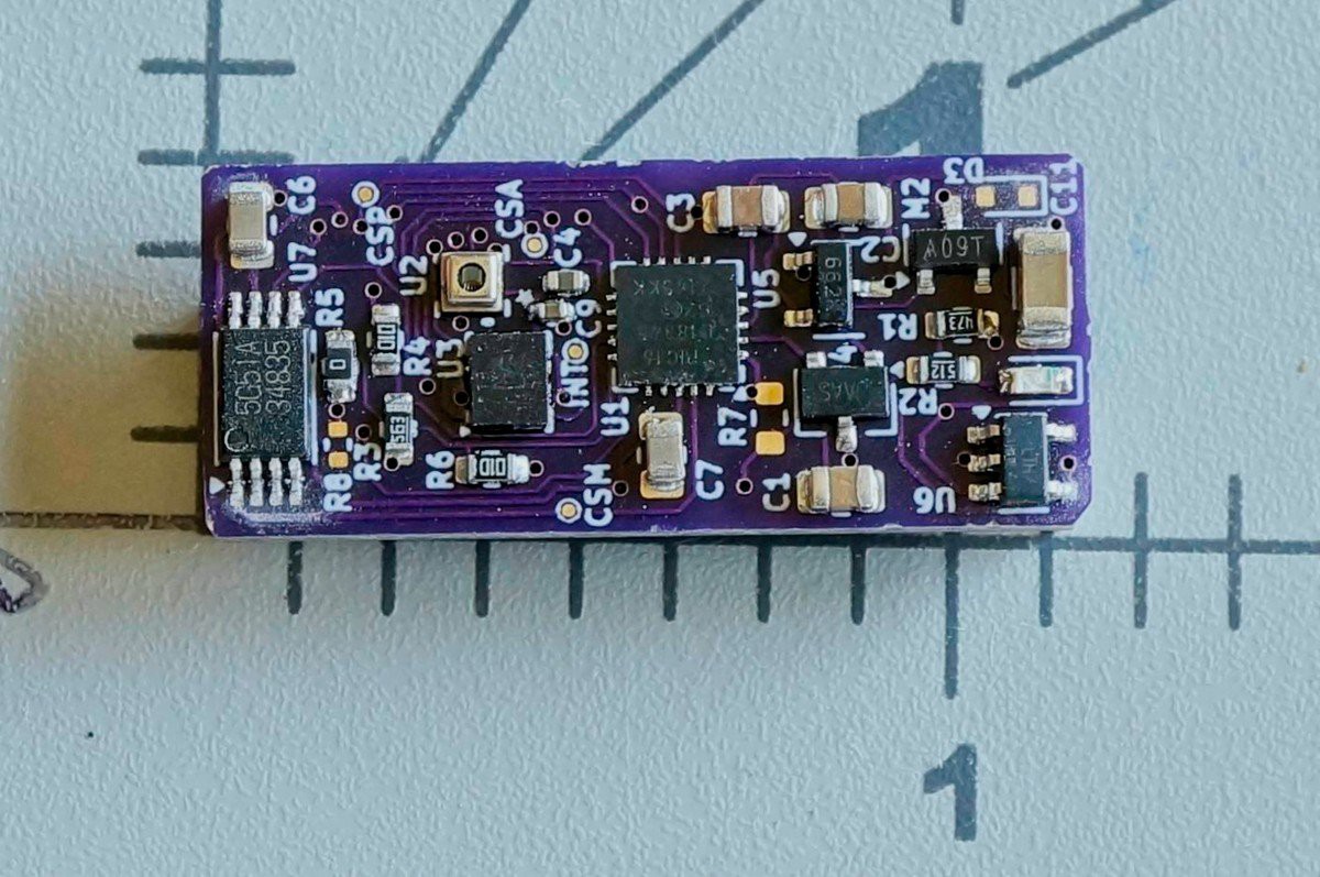
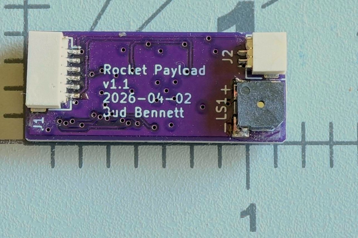
    I built three v1.1 prototypes. These are roughly 12.5mm x 30mm (2 layer PCB) and weigh 2.0g. Pretty small and light for what they do. That BMP384 pressure sensor (the metal can with the hole in the top) is only 2mm x 2mm, with 10 pads underneath. It is nearly impossible to solder -- I must create solder bumps on both the BMP384 and the PCB, then slather gooey solder flux over the PCB pads to keep the part in place while I heat it with the hot air gun. That part, and the LSM6DSO32, are the first parts soldered onto the PCB. I then test the connection by verifying the input protection diodes exist between GND and the pads before moving on to soldering the rest of the components. This method is tried and true for me, but is time consuming.

    Image
    Image

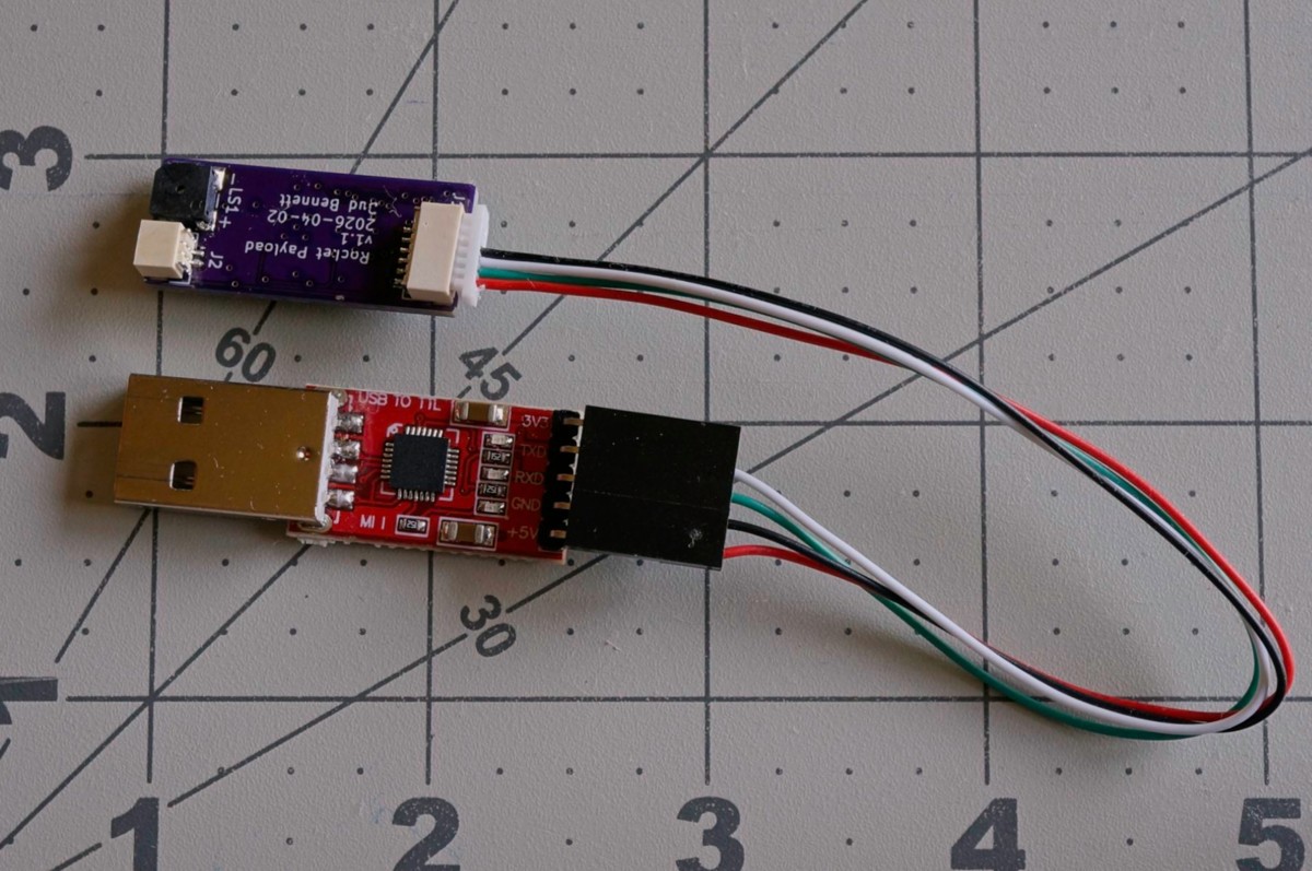
    At first, I thought that it would be simpler/easier to purchase a CP2102 USB-to-UART adapter board to interface from the computer/phone. Adding the CP2102N component was expensive, and big, so I outboarded it. A CP2102 breakout board is relatively cheap and available (<$7 at Amazon.) I regretted this decision the moment I saw a potential user attempt to get the Win11 drivers installed on his laptop. The CP2102 adapter was listed as "Other" in the device list and we couldn't get it properly located as a PORT. 

    The other issue is that it required a custom harness that wasn't exactly pretty:

    Image

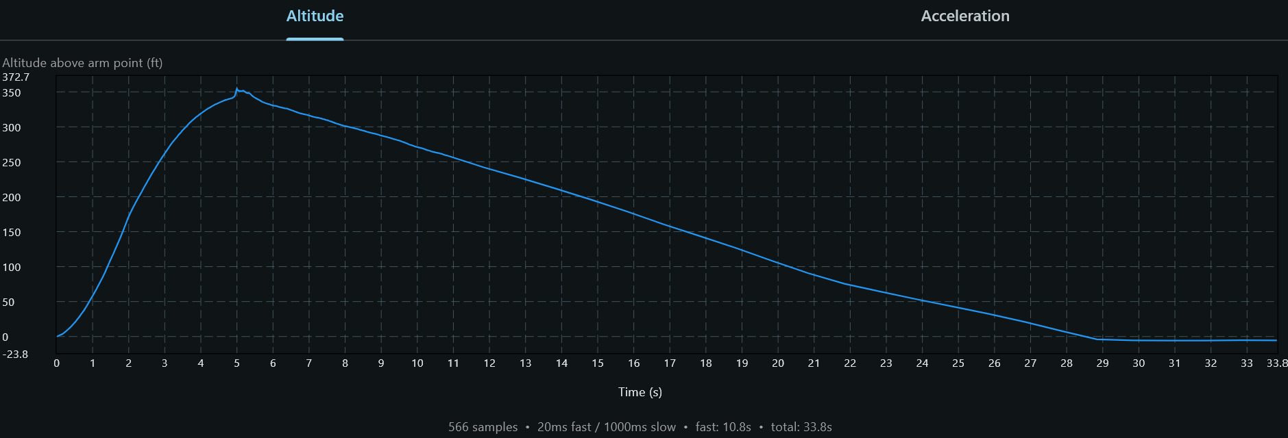
    I was testing performance either by tossing it by hand a few feet into the air, catching it, and placing it on a desk until it completed the flight. I also attached it to one of my quad copters to get more altitude. The v1 prototype did get a chance to record one rocket flight. It was a pretty large model with a separate payload section having vent holes drilled into it. I expected strange artifacts to appear from unknown sources, but the result was a pleasant surprise:

    Image

    I don't know why that step in altitude appears at apogee. My suspicion is that the barometer is susceptible to the mechanical shock from chute deployment -- the payload was not very well secured in the payload section and could have dislodged to rattle around. The sample intervals change from 20ms to 1s at 10.8s but there is no visible artifact from that and the descent is tracking nicely without noise. It is hard to make a case for changing any electrical parameters.

    v1 Upgrades:

    After the first prototype PCBs were populated, there were a few features added to improve performance and/or the user experience:

    Firmware Changes:

    1. A first-order temperature compensation was applied to the raw pressure data when calculating apogee and landing. The temperature can change dramatically during a flight, especially if the Payload is not enclosed within a separate payload section of the rocket and is exposed to ambient conditions after chute deployment.
    2. Every 5 seconds the launch altitude value is updated to prevent drift if the rocket isn't launched immediately after arming.
    3. After arming, the PIC collects 500ms of data (25 samples) in a ring buffer. This data is prepended to the flight data to show a complete picture of the launch prior to the detection threshold. The gyro data is just loaded with zeros.
    4. Added user selectable parameters: Fast sample data rates (50Hz, 25Hz, 12.5Hz, 6.25Hz), Fast sample rate duration, Accelerometer filter bandwidth, Launch confirmation debouncing.

    Application Changes:

    1. The application calculates flight parameters (doesn't rely on the PIC's calculations) to yield more accurate numbers.
    2. Incorporates the FW changes above into the settings and charting.
    3. Created native apps for Android, Ubuntu Linux, Raspberry Pi OS. (Can't do MacOS until I find a willing Mac user.) The Android app doesn't include any graphics -- it's a pretty tiny display anyway -- its primary purpose is to download flight data while in the field and reset the Payload to record another flight (it does, however display calculated flight stats.)

    Each significant upgrade was released to Github. At the time of this writing...

    Read more »

View all 6 project logs

Enjoy this project?

Share

Discussions

Similar Projects

Does this project spark your interest?

Become a member to follow this project and never miss any updates

Image