Image

Going On A Tangent With The Intel 8087’s Hybrid CORDIC Algorithm

Continuing their reverse-engineering of Intel’s 8087 FPU, [Ken Shirriff] and friends took a look at one of the trigonometric functions, specifically FPTAN.  The most exciting part with such reverse-engineering is probably figuring out which algorithm was used in the implementation, while trying to determine the reasoning behind the final hardware design.

If you’re running a simple MCU or MPU like the 6502 or Z80 without hardware functions you’d likely use an algorithm such as CORDIC or similar, as this requires only basic hardware features like addition, subtraction, bitshift, and look-up tables. One can also use polynomial approximation if there’s hardware support for a potential speed-up, or as is the case in the 8087, create a hybrid approach that targets speed and accuracy.

In the article the exact implementation to get to 64 bits of accuracy is detailed, starting with the 16 bits calculated using CORDIC before switching to the Padé approximant technique involving the ratio of two polynomials. Since after calculating the brunt of the final value with CORDIC the remainder is a fairly small value, this polynomial approximation is not just very accurate but also fast.

This approach allows the FPTAN and similar trigonometric functions in this FPU to hit a very high level of accuracy and not require the look-up table sizes and additional time required to work through the remaining bits with CORDIC. For those who want to see the full algorithm Intel’s engineers used, [Ken] has the full microcode listing with comments in the article as well.

As for the exact speed-up from this approach, [Ken] calculates for one value that FPTAN would spend 33% on CORDIC pseudo-division, 47% on CORDIC pseudo-multiplication and a mere 15% on the polynomial approximation along with about 5% overhead.

With the Pentium series of CPUs Intel moved completely away from CORDIC, as it’s clear that as accurate as it may be, it’s hard to scale to a significant number of bits without incurring significant time penalties. With the introduction of SIMD instructions the x87 ISA has further seen its functionality reduced, but this analysis shows once again why the 8087 made such an impact when it was released.
Image

Reconstructing Device Firmware From SPI Reads

If you wanted to extract the firmware from a mystery device, you might pull the flash chip out of it and toss it into a reader. But if you only had one chance to get it right and couldn’t risk damaging the device in the process, physically removing the chip may seem much less attractive. Reading the chip in-circuit failed — because of course it did — so what does that leave?

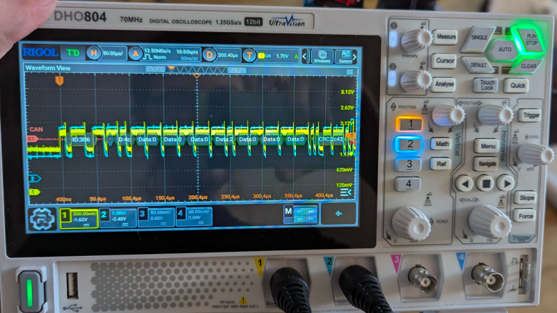
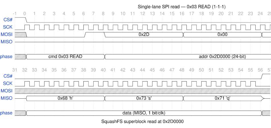
Well, if you follow the example of [Matthew “wrongbaud” Alt], the next tool you reach for might be a logic analyzer. In a recent write-up, [wrongbaud] explains the process of identifying, capturing, and ultimately decoding the SPI read operations used to load the firmware from a common W25Q-series flash chip at boot time. He notes it’s not a perfect solution, as in the end you’ll only be able to sniff out what the CPU actually reads, not necessarily the entire contents of the chip, but it’s a big step in the right direction if you’re reverse engineering something in the dark.

Continue reading “Reconstructing Device Firmware From SPI Reads” →

Image

Reverse Engineering A Sony Car Stereo LCD

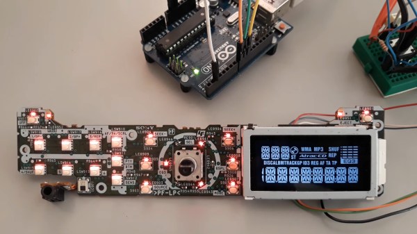
For his own reasons, [Jose Luis Monteiro] (aka [emsyscode]) decided he needed to drive the LCD on a Sony CDX-A250 car stereo’s front panel using an Arduino. There’s probably a sweet project in the works, or perhaps he just wanted to see if it could be done. Either way, more power to [Jose], because he totally pulled it off and put the results up on GitHub for all to enjoy. There’s also a project video showing how he did the reverse-engineering, which you can see below.

The driver for this diminutive LCD is a chip obviously labeled LC75826W, and that’s what the Arduino ends up talking to. Thankfully, there was a datasheet available for that part, which gave [Jose] a great starting point for figuring out how to use it. While [Jose] is working with the LC75826W driver, he’s quite explicit in his GitHub repo that this repository is not a driver library for that chip. The code only targets the specific LCD on the CDX-A250 head unit. Still, if you’ve got a different oddball LCD that uses this driver, [Jose]’s code is a great place to start, and since it’s under an MIT license, you can fork to your heart’s content.

Kudos to Sony for not obfuscating the part or using a chip-on-board black blob — you can reverse-engineer an LCD driven by one of those, but it’s a lot more work. If you’re wondering how and why those black blobs come to be, we’ve got you covered.

Continue reading “Reverse Engineering A Sony Car Stereo LCD” →

Image

Rusting An E-scooter (In A Good Way)

It is a classic Hackaday situation. You have an Egret GT E-scooter. It has a screen that shows the usual dash stats, but that led to an annoyance. You could accidentally enter firmware update mode and, from there, enter operational mode without the security PIN. [Ben] couldn’t let that stand, so he reverse-engineered the protocol and rewrote the firmware in Rust. As he put it, “… because I have to break… everything I own…” We get it.

The mobile app was useful for some basic info, since sniffing Bluetooth is fairly easy and analyzing mobile code is, more or less, straightforward. Analysis revealed some data that doesn’t show on the display and that several things are sent back to home base tagged with the scooter’s unique ID — another reason to gut the existing firmware.

Continue reading “Rusting An E-scooter (In A Good Way)” →

Image

Analyzing The FScale Instruction In Intel’s 8087 FPU

During his continuing analysis of the architecture and microcode of Intel’s highly influential 8087 floating point unit (FPU) co-processor, [Ken Shirriff] has now arrived at the point where he can put together how the 8087’s microcode implements various x87 instructions. One of these, the FSCALE instruction turned out to be far more complicated than assumed, with one might assume to be a straightforward powers-of-two scaling turning out to entail over 140 micro-instructions and three levels of sub-routine calls just to handle all cases.

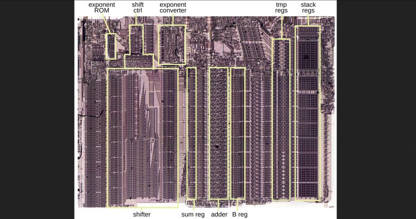
The annotated die shot in the heading image shows the functional blocks that are used by this one x87 instruction, to give some kind of idea of what amount of hardware even ‘just’ scaling a floating point number involves.

Much like with the x86’s CISC-style ISA, these 8087 instructions break down into individual steps that involve everything from loading values into registers, performing operations, checking for and handling error conditions as well as stack management. As can be seen in [Ken]’s breakdown of the FSCALE implementation in the 8087 it’s all very logical, taking a high-level instruction and doing all that’s needed for a robust implementation, without bothering the developer with the details.

Of note is that the 8087’s implementations led to the IEEE 754 floating point standard, providing what definitely at the time was one of the most mathematically accurate FPUs that somehow still was financially responsible enough to make it into a relatively affordable PC.

Image

Reverse Engineering The Philips PM5139

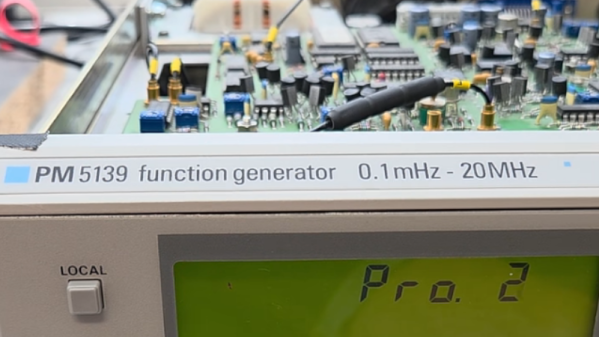
The Philips PM5139 is not famous. It won no great victories on the battlefield, nor was instrumental in changing the political landscape. It was just a useful function generator that you might find on a workbench somewhere, doing its job quietly and relatively accurately. [doctormord] has been doing the work to reverse engineer this humble piece of hardware.

The PM5139 is poorly documented; the only existing service manual out there is for the PM5138A, a less-capable sister model. Hence, there was some value in reverse engineering the device to understand it better. Work started with two EPROM dumps capturing what Philips put in the box all the way back in the early 1990s. From there, the code was examined and tinkered with until [doctormord] felt confident to modify it and improve upon what was already there. This was achieved with the aid of an 8051 emulator that could run the code to make it obvious what was going on. The result was a custom “V2.0” firmware that adds six arbitrary waveforms to the function generator and the ability to play simple music, amongst other tweaks.

We love to see old hardware given new functionality, even decades down the line, and we love some good reverse engineering, too. Video after the break.

Continue reading “Reverse Engineering The Philips PM5139” →

Image

Decoding The NEC V20 Microcode ROM

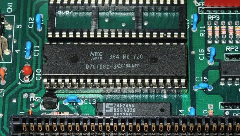
The NEC V20 is an Intel 8088-compatible processor that features the same use of microcode, though with its own characteristics. This makes it important to use this same microcode if your goal is to create a cycle-accurate emulator of this processor, as [GloriousCow]’s goal is. Cue decoding the microcode ROM in a die shot of this CPU, in order to create a usable ROM image.

As with any fabricated ROM you can technically do it by hand, the ROM section in the die shot contained 29,928 bits which even at a pretty zippy pace would take up a considerable amount of time to parse. Here you can divide-and-conquer by handing parts of the ROM off to good friends, or you can use automation and some machine vision and theoretically get an answer as soon as you have finished writing and testing the tool.

Close-up of some of the microcode bits.

Although [Travis Goodspeed]’s MaskRomTool exists exactly to automate bit detection, it was found that there wasn’t enough contrast in the die shot for it to work reliably. What it did provide were the locations of the bits and from it 42×42 pixel PNG files of each bit.

Next a convolutional neural network (CNN) was trained to determine the difference between a 0 and 1 bit. This still took the manual classifying of 1,000 images, but seemed to work fairly well. Although some bits were marked as ambiguous, it was easy enough to use Mark 1 eyeballs to run a classification on these handful of images than to tweak the CNN model.

With this microcode in hand it was then possible to match it against the V20’s internal architecture to fully determine what each part does. Although not quite finished yet, there’s a GitHub repository containing the progress so far.

The V20’s microcode has been the focal point of much legal fighting back when NEC and Intel were still duking it out in how far one could make a CPU compatible with that of a competitor.