Image

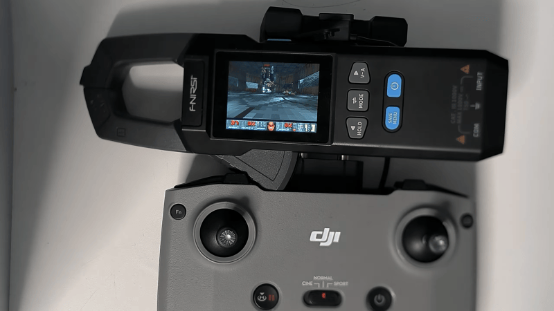
DOOM Ported To A $30 Clamp Meter

DOOM. Boil it, mash it, stick it in a stew, it’s the game that runs on anything and everything. Now, the classic shooter is running on a rather unlikely target—a cheap clamp meter of very limited resources, thanks to the work of [Artur Bieniek].

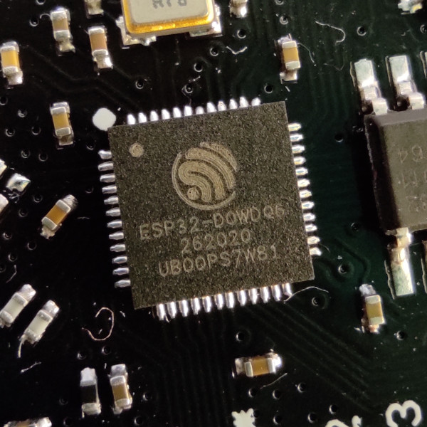
The clamp meter in question is the FNIRSI DMC-100, which can be had for the low price of just $30 or so if you know where to look. It’s a far cry from the many thousands of dollars you’d pay for a heavy old 486-based machine back in 1993. [Artur] got the doomgeneric engine running on the Artery AT32F415 chip that runs the clamp meter.

The chip is pretty capable, with its 150 MHz clock speed, though the 32 KB of RAM posed rather a big limitation to the project. It may be one of the lowest RAM DOOM ports out there. Even with this limit, [Artur] was able to get Episode 1 of Freedoom: Phase 1 loaded on to the thing, including E1M1 to E1M9 along with the title screen, intermissions, the finale, the menu, and four save slots. Color graphics are displayed on the meter’s 320 x 240 screen, and there are even sound effects on the built-in buzzer. Controls are mapped to the rather curious choice of a DJI RC-N1 drone controller.

We’ve seen DOOM running on everything from desk phones to completely custom CPUs. These days you have to try pretty hard to find something it hasn’t already been ported to.
Continue reading “DOOM Ported To A $30 Clamp Meter” →

Image

An Open Source Linear Capacitive Encoder

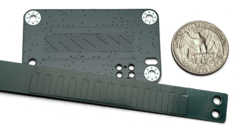
If you’ve ever pulled apart a set of digital calipers, you’ve probably marvelled at the capacitive encoder that does all the measuring work. There’s nothing stopping you from using the same techniques yourself, as [Nick] demonstrates with an open-source capacitive encoder of his own design.

The sensor PCB works by by having a grid of eight transmitting antennas, etched into a PCB, beneath a larger receiving antenna. The transmitting antennas pulse out a pattern as the sensor PCB moves, with the signals bouncing back from the reflector PCB which is fixed in place. The varying capacitance caused by the position of the reflector elements relative to the sensor PCB varies the strength of the pulses hitting the receiving antenna. A microcontroller—in this case an STM32—can read those pulses to determine the displacement of the sensor PCB relative to the reflector down to a very fine degree. In this case, to an accuracy of 40 micrometers. Not bad!

If you need ultra-fine linear tracking for something you’re building, you might find this project very useful. Files are available on Github for the curious, along with a great explainer on exactly how the capacitive coupling becomes a positional reading. You can also study previous teardowns we’ve featured on cheap digital calipers, just to round out your education further. If you’re working on your own impressive workshop equipment, or subcomponents of such things therein, don’t hesitate to let us know on the tipsline!

Image

An Open Micro-Manipulator Improved

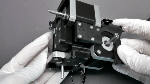
If you need a micro-manipulator, you probably already have a good idea of what it does. For example, you might be moving a probe over an IC die or wafer. You might be looking at something through a microscope. The key is moving something in very small, precise increments along three axes. An open-source design for a micro-manipulator has seen significant improvements lately. You can see several videos about the device below.

The device uses stepper motors, parallel kinematics, and miniature ball joints to achieve precise motion. The recent version 4.0 update fixes a few problems. According to the GitHub page:

  • Self-collision during homing fixed.
  • Connection of the ball joint block with screws only was not well constrained and could be rotated a bit.
  • No reliable way to ensure consistent linkage rod length
  • Unnecessary ball joint friction
  • Accurate ball position heavily dependent on print quality and corner rounding
  • Rubber bands could not be changed or removed once glued in.

Continue reading “An Open Micro-Manipulator Improved” →

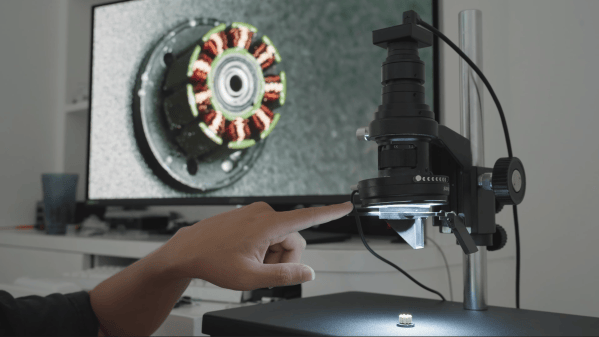
A man's hand is seen adjusting a lever connected to a lens, which is pointing down towards the windings of a small motor. A screen behind this shows an image of the windings, taken from an angle slightly to the side.

Building A Microscope With A 3D View

As electronic components grow ever smaller, a microscope has become an increasingly indispensable tool for any fine work; when inspecting electronics, though, especially solder joints, [Corebb] found a top-down view too limiting, so he built his own microscope with a rotating side-angle view.

The microscope itself is made of a commercial C-mount microscope lens assembly and a USB camera; the lens has a variable magnification factor up to 200x, which is plenty for electronics work, and is mounted on an adjustable stand to move the focal point. This is paired with an LED ring for illumination and two polarizing filters, one mounted on the lens and one one the lighting ring; when adjusted to 90 degrees from each other, these eliminate glare from reflective surfaces.

To view subjects from the side, [Corebb] built a snap-on adapter. This uses a pair of mirrors to capture a view from the side of the object and direct this through the main microscope lens. An additional concave lens compensates for the increased length of the optical path, and ball bearings let the whole adapter rotate around the microscope and capture the subject from any angle. [Corebb] tried 3D-printing the adapter, but found that flexing caused too much jitter; in addition to being sturdier, a machined aluminium part reduced shadows by allowing for thinner supports. The adapter snaps onto the microscope with small magnets, which keep the optical path consistently aligned.

This isn’t the first time we’ve seen a soldering microscope with a view from the side, but this does look much more affordable. If you’d like to try the polarized light source with your microscope, we’ve covered that before.

Image

Hand-Machined Stake Sharpener Just In Time For Dracula Season

Vampires aren’t as common as they once were, but in most places they aren’t fully protected and it’s still possible to get a tag for legal hunting come October — at least if you’re using traditional weapons, like a good old wooden stake.

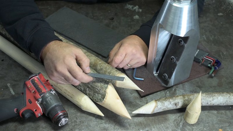
[This Old Tony] on YouTube didn’t have a good old wooden stake handy, but he does have a machine shop. Does he turn stakes on a lathe? Hardly. He turns an aluminum block into a giant pencil sharpener so he can use his drill to make vampire-removers out of any stick he finds.

If you thought that intro was too silly, you can skip the video. [Tony] is a funny guy, and is obviously enjoying himself in the voice over. He also obviously knows his way around a machine shop, and the 22 minute video shows every step of making a tool from a solid block of aluminum and some steel plate. It isn’t as soothing as some machinist’s videos are, though, as roughing out the 30 degree interior cone that will hold the stake against the steel blade is somewhat nerve-wracking to watch. Getting the blade mount tangent to the cone may have been trickier machining overall, but [Old Tony] nails every step. He’s now ready to dust any Nostferatu or Lasombra who darkens his door, assuming he has the strength to hammer the 3″ stakes he’s making through their undead ribs.

We’ve been enjoying [Old Tony] since we saw him build his own CNC table, only to ignore it in favour of his hard-earned skills. If you like that sort of thing, take a look — [Tony]’s cutting wit can make even videos about boring tools entertaining.

Continue reading “Hand-Machined Stake Sharpener Just In Time For Dracula Season” →

Image

Belt File From Old Mixer And Junk Bin Parts

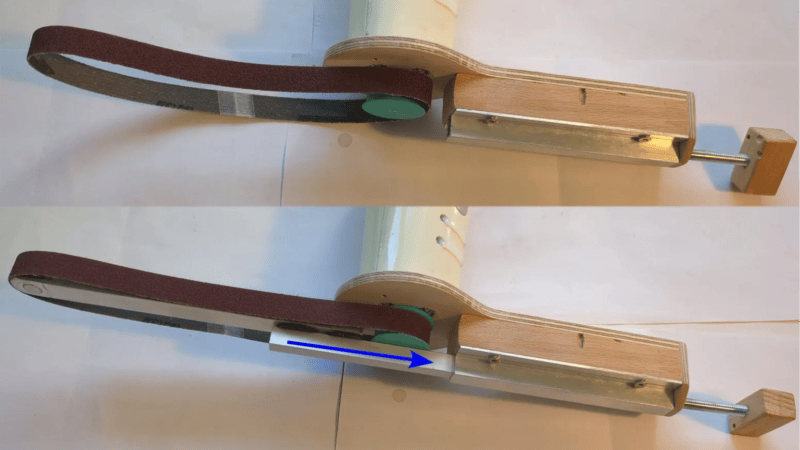
Making one’s own power tools can be a rewarding way to upcycle parts, and [bluesyann] does exactly that with a belt file made from an old mixer. We like how the enclosure for the old mixer is preserved and acts as a handle, so there’s no need to worry about motor mounting and wiring separately. It looks perfectly usable, and all the hardware needed is the sort of thing one finds in a scrap pile.

[bluesyann] stretches the sanding belt between a 3D printed pulley attached to the mixer motor, and a bearing fitted into the end of some aluminum U-channel. Scrap wood and more nested U-channel make up the rest of the assembly, and there’s even a tension adjustment made from a threaded rod.

There’s a bill of materials and a 3D model for the pulley, but a build like this is more about sharing the broad strokes rather than the exact design. Whenever one modifies or integrates an existing piece of equipment (the mixer, in this case) into a project, most of the work is about working with and around the bits one can’t change.

Watch it in action in a brief video, embedded just below. If you like the idea but don’t have a mixer like the one [bluesyann] used, let us point you toward a similar DIY attachment to get a similar result from a common angle grinder.

Continue reading “Belt File From Old Mixer And Junk Bin Parts” →

Image

Building A DIY Centrifuge For Blood Processing

If you want to do certain types of lab work with blood, you’ll need a centrifuge. It’s often possible to find serviceable units on the used market, but they may not meet your requirements if you’re doing something quite specific. For that reason, [Thomas Nguyen] decided to build his own centrifuge from scratch.

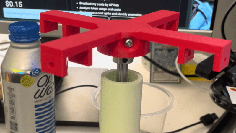
His goal was to separate T cells from blood for further lab analysis, and he needed to be able to work with blood in 15 mL conical tubes. Capable centrifuges weren’t affordable, but he figured he could build his own quite easily. To that end, he enlisted a Raspberry Pi Pico, a 3D printer, and an A2212 brushless motor with a 30 amp electronic speed controller.

Soon enough, he had a design for a fixed-angle centrifuge design that could spin up blood products to the required speed for separation. It has useful safety features, like an MPU-6050 for vibration detection to shut down in case of dangerous imbalance, and an IR sensor for monitoring and controlling rotational speed. For now, the project is still in development, with the first version built and spinning. [Thomas] aims to check that the build operates safely and can separate fluids like dyed water and glycerol successfully before running it with real blood products.

We’ve seen other successful DIY centrifuge builds before, too. Sometimes, the lab hardware you need is the lab hardware you build yourself. If it works and does the job safely, it can be all that you need to get your science goals coming to fruition.

Continue reading “Building A DIY Centrifuge For Blood Processing” →