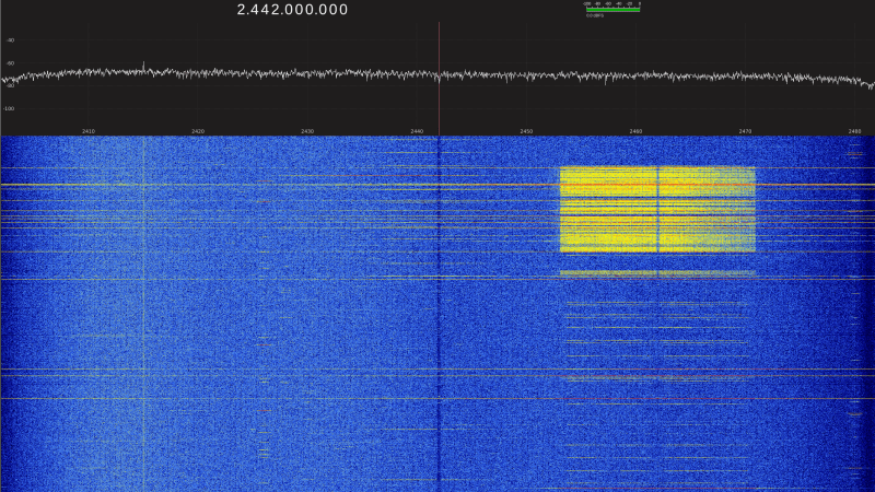
A waterfall display is shown, with a prominent yellow block in the upper right corner of the display.

Turning A Wi-Fi Adapter Into An SDR

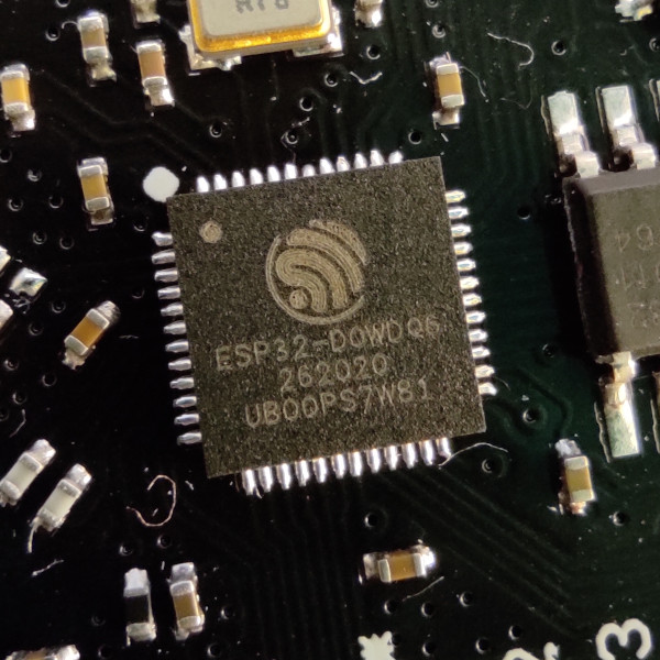
Since the discovery of an undocumented I/Q sampling feature in ESP32 chips about two weeks ago, there’s been a flood of similar features being found in other wireless chips, including LoRa and Wi-Fi chipsets. The latest chip to join their ranks is the MediaTek MT7921AU, often used in Wi-Fi adapters, with two different projects developing independent SDR drivers for it in the last few days.

The first was BirriaSDR, which discovered that the chip exposes raw I/Q samples for debugging and calibration; BirriaSDR instead streams these to the host at 40 Msps in 14-bit resolution, with the option to tune from 2156 to 2610 MHz. BirriaSDR uses libusb to directly communicate with the Wi-Fi adapter and access its registers; it doesn’t make any permanent firmware changes, so the Wi-Fi adapter goes back to its original state after being used as an SDR. BirriaSDR implements an API similar to the RTL-SDR’s.

Mtk79ICAP, by contrast, exposes the MT7921AU’s sampling features over a standard SoapySDR interface. Unlike BirriaSDR, it applies some firmware changes to the chip, and it requires a modified driver to work. However, it can reach a maximum bandwidth of 80 MHz and tune to the 5 GHz bands. The Wi-Fi adapter in use can also simultaneously work in monitor mode and stream SDR data, though this only works when automatic gain control is enabled.

This is the second MediaTek chip we’ve seen repurposed for SDR work, after the earlier MT7996. Conveniently, Wi-Fi adapters often have external antennas, which should make it easier to connect a frequency mixer circuit. These adapters aren’t quite there yet, but some hackers have already used the ESP32 to transmit arbitrary signals.

Image

Introducing FISSURE: A Toolbox For The RF Hacker

No matter what the job at hand is, if you’re going to tackle it, you’re going to need the right kit of tools. And if your job includes making sense out of any of the signals in the virtual soup of RF energy we all live in, then you’re going to need something like the FISSURE RF framework.

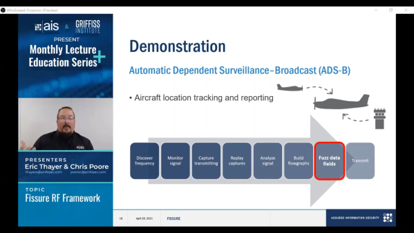
Exactly what FISSURE is is pretty clear from its acronym, which stands for Frequency Independent SDR-Based Signal Understanding and Reverse Engineering. This is all pretty new — it looks like [Chris Poore] presented a talk at DEFCON a few weeks back about using FISSURE to analyze powerline communications between semi-trucks and their trailers, and they’ve got a talk scheduled for next month’s GNU Radio Conference as well. We’ve been looking through all the material we can find on FISSURE, and it appears to be an RF hacker’s dream come true. They’ve got a few examples on Twitter, like brute-forcing an old garage door opener with a security code set by a ten-position DIP switch, and sending tire pressure monitoring system (TPMS) signals to a car. They also mention some of the framework’s capabilities on the GitHub README; we’re especially interested in packet crafting for various protocols. The video below has some more examples of what FISSURE can do.

It looks like FISSURE could be a lot of fun, and very handy for your RF analysis and reverse engineering work. If you’ve been using Universal Radio Hacker like we have, this looks similar, only more so. We’ll be downloading it soon and giving it a try, so be on the lookout for a hands-on report.

Continue reading “Introducing FISSURE: A Toolbox For The RF Hacker” →

Image

DSP Spreadsheet: IQ Diagrams

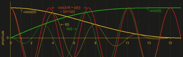
In previous installments of DSP Spreadsheet, we’ve looked at generating signals, mixing them, and filtering them. If you start trying to work with DSP, though, you’ll find a topic that always rears its head: IQ signals. It turns out, these aren’t as hard as they appear at first and, as usual, we’ll tackle them in a spreadsheet.

What does IQ stand for? The I stands for “in phase” and the Q stands for quadrature. By convention, the I signal is a cosine wave and the Q signal is a sine wave. Another way to say that is that the I and Q signals are 90 degrees out of phase. By manipulating the amplitude of I and Q, you can create complex modulation or, conversely, demodulate signals. We’ll see a spreadsheet that shows that completely next time.

Continue reading “DSP Spreadsheet: IQ Diagrams” →

Image

If The I And Q Of Software Defined Radio Are Your Nemesis, Read On

For those of us whose interests lie in radio, encountering our first software defined radio must have universally seemed like a miracle. Here is a surprisingly simple device, essentially a clever mixer and a set of analogue-to-digital or digital-to-analogue converters, that can import all the complex and tricky-to-set-up parts of a traditional radio to a computer, in which all signal procession can be done using software.

A quadrature mixer. Jugandi (Public domain).

When your curiosity gets the better of you and you start to peer into the workings of a software defined radio though, you encounter something you won’t have seen before in a traditional radio. There are two mixers fed by a two local oscillators on the same frequency but with a 90 degree phase shift, and in a receiver the resulting mixer products are fed into two separate ADCs. You encounter the letters I and Q in relation to these two signal paths, and wonder what on earth all that means.

Continue reading “If The I And Q Of Software Defined Radio Are Your Nemesis, Read On” →