

Arctos Robotics Documentation
Build your own robotic arm, low-cost high-performance mobile robot, or Arctos Studio workflow. Open source, 3D printed, and community driven.
Use the dropdown in the top bar to choose between Open loop, Closed loop, Mobile, and Studio documentation.
Start with the Quick Start Guide to get an overview of the build process, estimated time, and required skills.
Project Overview
Arctos documentation covers the robot arm in open loop and closed loop configurations, the MX1 Mobile robot platform, and Arctos Studio software workflows.
Control system without position feedback. Simpler to build and program, ideal for beginners learning robotics fundamentals.
Advanced control system with encoder feedback for precise positioning. More capable but requires additional configuration.
Low-cost, high-performance mobile robot capable of SLAM, AI control, and perception using an old phone camera, LiDAR, or depth camera.
This documentation focuses on the Closed Loop system as it represents the latest improvements. Use the version selector in the header to switch between control systems.
Use the Mobile option in the selector to view MX1-specific BOM, wiring, assembly, software, and 3D printing instructions.
At a Glance
Join the Community
Get help, share your build, and connect with other makers:
Quick Start Guide
Everything you need to know before starting your Arctos build.
Please read the entire Safety section before starting. This robot uses high currents that can cause burns or electrical shock if mishandled.
Build Overview
Build Steps
Order parts from the BOM, prepare your 3D printer, and gather required tools (Allen keys, soldering iron, pliers).
Print test_print.stl to verify your printer settings and hardware fitment before printing all 168 parts.
Print parts axis by axis (X→Y→Z→A→B→C). Gearboxes first, cover panels last. Expect 80-100 hours of print time.
Build the cycloidal (Y, Z axes) and planetary (A, B, C axes) gearboxes. Follow the 3D assembly manual carefully.
Configure MKS drivers, glue magnets to motor shafts, and prepare all wiring BEFORE mounting motors.
Assemble each axis following the interactive 3D manual. Install belts, endstops, and wiring.
Flash firmware, configure Arctos Studio, calibrate each axis, and run your first program!
Pre-Build Checklist
- 3D printer calibrated and working (0.4mm nozzle recommended)
- 4kg of PLA filament (2 colors for two-tone look)
- Hardware kit ordered or parts sourced from BOM
- Allen keys (2.5, 3, 4, 6mm), pliers, tweezers ready
- Soldering iron and solder available
- Read the Safety section completely
- Joined Discord for community support
3D Printing Checklist
- Printed and tested test_print.stl for fitment
- All X axis parts printed
- All Y axis parts printed
- All Z axis parts printed
- All A axis parts printed
- All B axis parts printed
- All C axis parts printed
- Gripper parts printed
Assembly Checklist
- Y axis cycloidal gearbox assembled
- Z axis cycloidal gearbox assembled
- A, B, C planetary gearboxes assembled
- Magnets glued to all motor shafts
- X axis fully assembled
- Y axis fully assembled
- Z axis fully assembled
- A axis fully assembled
- B axis fully assembled
- C axis fully assembled
- Gripper assembled and mounted
Electronics & Software Checklist
- All drivers configured with correct IDs
- All wiring completed and checked
- Endstops installed and tested
- Firmware flashed successfully
- Software installed and configured
- All axes calibrated
- First successful movement test
- First program executed successfully
Required Skills
| Skill | Level Required | Notes |
|---|---|---|
| 3D Printing | Intermediate | Must be able to print with supports, adjust settings |
| Soldering | Basic | Wire tinning and basic connections |
| Electronics | Basic | Understanding of power, ground, signal wires |
| Mechanical Assembly | Intermediate | Patience with small parts and tight tolerances |
Head to the Bill of Materials to order your parts, or check the 3D Printing section to start printing!
Review the Safety section and verify the MX1 wiring diagram before applying battery power.
Mobile Build Overview
Build Steps
Open the Mobile BOM, prepare printed plates, and keep parts grouped by assembly stage.
Follow the interactive manual, dry-fit the main frame, then install the drive hardware.
Use the MX1 wiring diagram, verify polarity, and power up the robot in stages.
Install an old phone camera for neural depth estimation, or fit LiDAR/depth camera hardware.
Bring up drive control, validate sensors, then start SLAM and AI-control experiments at low speed.
Mobile Pre-Build Checklist
- Mobile BOM reviewed and parts ordered
- MX1 print plates printed and inspected
- Assembly manual opened and build order understood
- Wiring diagram checked before battery connection
- Perception option selected: phone camera, LiDAR, or depth camera
âš ï¸ Safety First
Critical safety information you MUST read before building or operating the Arctos robot.
This robot can electrocute you. Make sure all wires are secured before turning on power. Never work on the robot while it’s powered.
Electrical Safety
- Always disconnect power before working on wiring or electronics
- Tin all wire tips and secure them firmly in terminals to prevent short circuits
- Check polarity carefully — reversed polarity will permanently damage MKS drivers
- Use appropriate wire gauges — thin wires can overheat and cause fires
- Inspect connections regularly — loose connections generate heat
Stepper motors running at high current can get extremely hot. Adjust current limits to prevent overheating. If a motor is too hot to touch, reduce the current immediately.
Mechanical Safety
- Robot joints can pinch and crush — keep fingers clear during operation
- Gearboxes have significant torque — they can cause injury if fingers get caught
- Use caution when removing supports — sharp tools can cause cuts
- 3D printer and soldering iron — standard hot tool safety applies
- Wear safety glasses when removing supports or working with small parts
Safe Operation
- Always start with slow movements when testing
- Keep the work area clear of obstacles
- Never leave the robot running unattended
- Install and test endstops before full operation
- Have an emergency stop plan (power switch accessible)
- Bolt the robot to a secure surface — the robot can tip over during operation if not properly secured
Common Mistakes to Avoid
Consequence: Permanently destroys the MKS driver board instantly.
Prevention: Triple-check polarity before connecting power. Red to +, Black to -. When in doubt, use a multimeter.
Consequence: Motors overheat, can cause burns, damage motors, or start fires.
Prevention: Start with lower current settings and increase gradually. If motor is too hot to touch, reduce current.
Consequence: Driver is permanently damaged.
Prevention: Check orientation markings on driver and socket. The potentiometer usually faces a specific direction.
Consequence: Can damage driver or cause unexpected motor movement.
Prevention: Always power off before adjusting the potentiometer on stepper drivers.
Building a robot can be frustrating. Parts may not fit, prints may fail, and things may not work the first time. Take breaks, ask for help on Discord, and remember: every successful build had setbacks along the way!
Specifications
Technical specifications and parameters for the selected Arctos platform.
Dimensions & Capabilities

Software Compatibility
- Arctos Studio — Native control software with GUI, calibration, and programming
- Nvidia Isaac Sim — Advanced simulation and AI training
- ROS1 & ROS2 — Robot Operating System integration
- GrblGru — Open-source control software
- Robot Overlord — Visualization and control
- Matlab — Advanced kinematics and control
- Unity — 3D simulation (in progress)
Axes Nomenclature
Each axis has a specific name, joint designation, link name, and CAN ID:
| Axis | Joint | Link | CAN ID |
|---|---|---|---|
| X (Base) | joint1 | Link_1_1 | 01 |
| Y (Shoulder) | joint2 | Link_2_1 | 02 |
| Z (Elbow) | joint3 | Link_3_1 | 03 |
| A (Wrist 1) | joint4 | Link_4_1 | 04 |
| B (Wrist 2) | joint5 | Link_5_1 | 07 |
| C (Wrist 3) | joint6 | Link_6_1 | 06 |
Work Envelope

Denavit-Hartenberg Parameters


Gear Ratios
| Axis | Gear Ratio | Gearbox Type |
|---|---|---|
| X | 1:13.5 | Belt reduction |
| Y | 1:150 | Cycloidal |
| Z | 1:150 | Cycloidal |
| A | 1:48 | Compound Planetary |
| B | 1:67.82 | Compound Planetary |
| C | 1:67.82 | Compound Planetary |
MX1 Mobile Overview
Arctos MX1 Mobile is a low-cost high-performance mobile robot platform designed for autonomous navigation, SLAM, AI control, and robotics development in Arctos Studio.

Perception Options
- Old phone camera: Uses neural networks for depth estimation from a reused mobile-phone camera.
- LiDAR: Compatible with LiDAR-based mapping and obstacle awareness workflows.
- Depth camera: Can be used when hardware depth sensing is preferred over neural depth estimation.
Software Compatibility
- Arctos Studio – Integrated robot setup, control, and development environment.
- SLAM workflows – Build maps and localize the robot for autonomous navigation.
- AI control – Use camera/depth data and autonomy software for higher-level behavior.
Bill of Materials
Complete list of parts needed to build the selected Arctos platform.
The complete BOM with quantities, links, and prices is available at arctosrobotics.com/bom or on Google Sheets.
Pre-Made Kits
The easiest way to get started is with a pre-made kit:
All 168 3D printed parts, ready to assemble. Save 80+ hours of printing time.
Complete hardware kit with all electronics, motors, and fasteners.
Hardware kit available on Amazon for faster shipping in some regions.
Version Comparison
| Feature | Open Loop | Closed Loop |
|---|---|---|
| Position Feedback | No | Yes (encoders) |
| Cost | Lower (~$300) | Higher (~$500) |
| Wiring Complexity | More wires | Fewer wires (CAN bus) |
| Programming | Simpler (GRBL) | More complex |
| Precision | Good | Excellent |
| Payload | 1kg | 1kg |
Self-Sourcing Parts
You can also source parts yourself to save money or customize:
- Threaded rods: Buy 1m M4 rod and cut to length. Drywall anchors (4mm diameter) work as cycloidal pins.
- Bearings: Can be salvaged from old 3D printers or bought in bulk.
- Motors: If using different motors, adapt the CAD files to fit.
- Fasteners: Local hardware stores often have better prices than online.
Check the community mods page and Discord #showcase channel for alternative parts and modifications others have made.
Kit Contents Overview
Visit arctosrobotics.com/robot-kits to see all available kit options and what’s included.
Use the live Arctos Mobile bill of materials for the latest quantities, sourcing links, and component details.
Mobile BOM Overview
The MX1 Mobile build combines printed structural plates, drive electronics, perception hardware, power distribution, and compute for SLAM and AI control.
Complete component list for building the MX1 Mobile robot.
Interactive assembly viewer for the Mobile platform.
Electrical layout for connecting the Mobile electronics.
Main Subsystems
- Mobile base hardware: Printed plates, frame parts, fasteners, wheels, and drive hardware.
- Electronics: Motor control, power distribution, battery, wiring, and safety switching.
- Compute and perception: Onboard compute with support for an old phone camera, ultrasonic sensors, LiDAR, or depth camera.
- Software integration: Arctos Studio setup for control, testing, and autonomous workflows.
3D Printing Instructions
Print settings, part orientation, and tips for successful prints.
Before printing all 168 parts, print the test_print.stl to verify hardware fitment. If parts don’t fit, adjust your printer settings or modify bearing clearances in the Fusion 360 file.
A 200x200mm print bed is required. Some users have printed on 180x180mm beds, but some parts needed to be separated into multiple pieces.
Recommended Print Settings
| Setting | Value | Notes |
|---|---|---|
| Material | PLA | PETG also works but may need adjustments |
| Nozzle Temp | 215°C | Adjust for your filament brand |
| Layer Height | 0.2mm | Balance of speed and quality |
| Extrusion Width | 0.4mm | Standard 0.4mm nozzle |
| Infill | 35% | Good strength without excess weight |
| Wall Count | 4 | Important for structural parts |
| Top/Bottom Layers | 4 | Solid top and bottom surfaces |
| Supports | Required | Many parts need supports – check each one! |

Bambu Lab Print Settings

Pre-Oriented Print Plates
The CAD files include pre-oriented print plates with all parts positioned optimally. Print the plates in order from bottom to top for the most efficient workflow.

Printing Order
Print gearboxes first, cover panels last. This lets you start assembly while still printing cosmetic parts.
Part Organization
- Parts are organized by axis: X → Y → Z → A → B → C
- Search the STL folder for axis name (e.g., “X”) to find all parts for that axis
- Total: 168 parts (some are duplicates like gears)
Part Naming Convention
Example: Z R lower core (1)_1-Z R lower core-stl.stl
- Z = Axis name
- R = Right side (L = Left)
- lower = Position (vs “upper”)
- core = Part type
- (1) = Can be ignored (export artifact)
Two-Tone Printing
For a professional two-tone look:
- Search for “cover”, “panel”, “pulley” → print in accent color
- Search for “core” → print in main color
- Check the Fusion 360 file or Discord #showcase for inspiration
Supports & Orientation
Many parts require supports. Some prints take 6-7 hours — discovering missing supports after the print fails is frustrating. Double-check every part in your slicer before printing.
Support Removal Tips
- Use a small flat screwdriver to pry supports
- Pliers help grip and twist supports off
- Utility knife for cleanup
- Orca Slicer creates easy-to-remove supports with good interface layers
Tolerances & Fit
Many holes are designed for tight fits with bolts. If parts don’t fit:
- Check your printer’s dimensional accuracy
- Adjust bearing clearances in the Fusion 360 source file
- Use a deburring tool or drill to clean up holes
- Try printing at 99% scale if parts are consistently oversized
Required Tools
| Category | Items |
|---|---|
| Allen Keys | 2.5mm, 3mm, 4mm, 6mm |
| Hand Tools | Pliers, tweezers, utility knife, lighter |
| Electric Tools | Soldering iron (or Wago clips as alternative), drill (optional) |
| Screwdrivers | Phillips, flat head |
| Other | Superglue, deburring tool, small hammer |
The MX1 Mobile parts are arranged as print plates. Most parts are designed to be printed without supports; only a few parts require supports, so check the sliced preview before starting each plate.
MX1 Print Plates

Recommended Print Settings
| Setting | Recommendation | Notes |
|---|---|---|
| Material | PLA or PETG | Choose a material that matches your expected payload and operating environment. |
| Layer Height | 0.2mm | Good balance of strength, surface quality, and print time. |
| Walls | 4+ | Use stronger perimeter settings on structural plates and motor mounts. |
| Infill | 35%+ | Increase infill for load-bearing parts if the robot will carry near its 15kg payload. |
| Supports | Only where needed | Most MX1 parts are designed support-free; enable supports only for the few parts that require them. |
Print Tips
- Print the largest plates on a well-calibrated bed with strong first-layer adhesion.
- Inspect holes and bearing seats before assembly; clean with a deburring tool if needed.
- Keep left/right parts organized by plate so the mechanical assembly follows the manual cleanly.
- Dry-fit major frame pieces before installing electronics or routing wiring.
Assembly Instructions
Step-by-step guides to assemble the selected Arctos platform.
Interactive Assembly Manual
The best way to follow assembly is with our interactive manual that shows each step in detail:
Interactive 3D web viewer with step-by-step instructions for the latest version.
Original PDF-style assembly manual for version 0.1.
Video Assembly Guide
This video is for v2.0. We are currently at v2.9.7. The main differences are in mounting the motors to A, B, C axes. Refer to the 3D assembly manual for the latest mounting instructions.
Assembly Timelapse
X Axis Assembly
More axis-specific assembly videos coming soon!
The following steps are not shown in the assembly manuals but are critical:
- Glue magnets on each stepper motor shaft
- Prepare and configure MKS driver wires BEFORE bolting motors
- Install on/off switch and LED indicator
Gearbox Assembly
Cycloidal Gearboxes (Y & Z Axes)
Cycloidal gearboxes provide high reduction ratios (1:24 per stage, 150:1 total) in a compact package. They’re ideal for 3D printing because they:
- Run quietly
- Have minimal backlash
- Don’t wear significantly over time
- Work well with FDM tolerances

Key Assembly Points:
- Three cycloidal disks rotate eccentrically at 120° to each other
- 25 stainless steel 4mm dowel pins on the outside
- 5 threaded rods on the inside contact bearings (618/6 for Y, 688 for Z)
- The last threaded rod should have resistance when inserting — this indicates correct assembly

Use a small 4mm dowel pin to lock the disks in alignment before installing them in the casing. Follow the camshaft part order and disk order shown in the manual.
Compound Planetary Gearboxes (A, B, C Axes)
Compound planetary gearboxes are lighter and achieve even higher reduction ratios than cycloidals. They’re used in the upper arm where weight matters most.
Trade-offs:
- Noisier during operation
- Require lubrication
- Experience more wear over time
Pay attention to the orientation of planetary gears during assembly — they must align as shown in the assembly manual images.
Additional Video Resources
Community members have created excellent build videos on their YouTube channels. Big thanks to these contributors:
If you get stuck, join our Discord server where the community can help troubleshoot assembly issues.
MX1 Mobile Assembly Manual
Use the interactive assembly manual below to build the MX1 Mobile base step by step. Keep the BOM and wiring diagram open during the electronics stages.
Launch the assembly viewer in a separate tab for more space.
Confirm hardware and electronics before each assembly stage.
Recommended Assembly Flow
- Print and inspect all MX1 plates before installing hardware.
- Assemble the mobile base mechanically and verify wheel alignment.
- Install motors, battery, power distribution, and controller hardware.
- Route wires cleanly, keeping power and signal paths strain relieved.
- Add perception hardware: old phone camera, LiDAR, or depth camera.
- Power on in stages, then connect through Arctos Studio for bring-up and testing.
Lubricate the gearbox gears with vaseline or graphite grease only after the gearbox assembly is complete. If lubricant is applied too early, it will spread onto your hands, fasteners, and surrounding hardware during assembly.
Wiring and Electronics
Complete wiring guides for the selected Arctos platform.
Reversing polarity can permanently destroy electronics. Triple-check all power connections before applying power. Tin wire tips and secure them firmly to prevent short circuits.
Components
- CANable adapter v2 — USB to CAN interface
- 4x MKS Servo 42D — Closed-loop drivers for smaller motors
- 2x MKS Servo 57D — Closed-loop drivers for larger motors
- 3x WSH231 — Dual hall effect sensors
- 6x KY-003 — Hall effect limit switches
Wiring Diagram

All components are daisy-chained from the CANable adapter to the C servo. Both ends of the chain require a 120Ω termination resistor.
Connect all wires to MKS drivers BEFORE bolting down the motors. Once mounted, there’s no space to add wires on A, B, and C axes.
Configuring MKS Drivers
Configure each MKS Servo driver with the correct CAN ID:
| Axis | CAN ID | Driver |
|---|---|---|
| X | 01 | MKS 57D |
| Y | 02 | MKS 57D |
| Z | 03 | MKS 42D |
| A | 04 | MKS 42D |
| B | 05 | MKS 42D |
| C | 06 | MKS 42D |
Use this magnet mounting jig (by DavidD) to center magnets on motor shafts.

Port Remapping
MKS57D (X and Y axes)
No remapping needed — they natively support two limit sensors (IN_1 and IN_2). However:
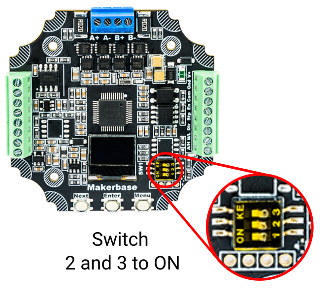
- Flip DIP switches 2 and 3 to “ON” to power the sensors
- Enable limits via MKS menu (“EndLimit”) or serial command 90
MKS42D (Z, A, B, C axes)
Requires pin remapping to use two limit switches:
Send via: Arctos Studio → Settings → MKS Settings → IO Control
Testing Endstops
- Put a magnet near each sensor — verify it lights up
- WITHOUT belt fitted, send HOME command or use MKS menu “GoHome”
- Motor should rotate slowly until sensor on IN1 triggers
- Send command to drive opposite direction, manually trigger other sensor — motor should stop
- When mounted, adjust sensor positions relative to magnets before fitting belt

Components
- Arduino Mega 2560
- 2x CNC Shield V3
- 6x TMC2209 stepper drivers
Wiring Diagram

Control Commands
The open loop version uses GRBL firmware and accepts G-code commands. Use RoboDK postprocessor for Arctos to generate code in this format:
- F800 — Feedrate (adjust as needed)
- G90 — Absolute coordinates (vs G91 relative)
Stream G-code to Arduino using Universal Gcode Sender or similar software.
Configuration Videos
Open Source Closed Loop Drivers (In Development)
We are developing open source closed loop motor drivers called CLMD (Closed Loop Motor Driver):

Learn more and contribute: github.com/Arctos-Robotics/CLMD-Closed-Loop-Motor-Driver
MX1 Mobile Wiring Diagram
Follow the MX1 wiring diagram for power distribution, drive electronics, compute, and perception hardware. Verify polarity and fuse protection before connecting the battery.

Main Electrical Subsystems
- Drive system: Connect the motors and motor controller according to the official wiring diagram.
- Power system: Route battery power through the specified switch, protection, and distribution points.
- Compute: Connect the onboard computer used for Arctos Studio integration, SLAM, and AI control.
- Perception: Add an old phone camera for neural-network depth estimation, or connect LiDAR/depth camera hardware when using those sensing options.
Before full power-up, adjust the TMC2209 driver reference voltage to 2.4V. Set the LM317 output in the 3.3V to 5V range required by your wiring configuration, then verify the result with a multimeter.
Power the robot in stages: first validate battery voltage and distribution, then motor control, then compute, and finally sensors. This makes wiring mistakes easier to isolate.
Gripper Setup
Wiring and control instructions for the Arctos gripper.
Setup Steps
- Download and flash Arduino Nano with code from HERE
- Adjust DC-DC converter voltage to 6V
- Connect according to the diagram below

Control Commands
Control the closed loop gripper using these commands:
Fully open the gripper
Fully close the gripper
Wiring to Arduino
Connect the DS3225 servo motor to the Arduino:
- Red wire (+) → 5V on CNC shield (top right corner, yellow)
- Black wire (-) → GND on CNC shield (blue)
- White wire (signal) → Pin 6 on Arduino Mega

Control Commands
Control the gripper with M97 command:
Fully close the gripper
Fully open the gripper
Parameter Explanation
| Parameter | Range | Description |
|---|---|---|
| B | 0-499 | Position value. For angle conversion: B = angle × 1.38 (499/360) |
| T | seconds | Time to complete the movement |
Software Setup
Firmware installation and software configuration guides.
Software Architecture
The Arctos robot uses a two-level software architecture:
- Low-level code: Firmware running on the microcontroller (GRBL for open loop, MKS firmware for closed loop)
- High-level code: Control software running on your PC (Arctos Studio, ROS, etc.)
High-Level Software Options
Native control software with GUI, calibration tools, and direct robot control.
Robot Operating System integration for advanced applications and research.
Low-Level: GRBL Firmware (Open Loop)
For open loop systems, flash GRBL firmware to the Arduino:
Requirements
- Arduino MEGA 2560
- USB cable
- GRBL firmware (unzip, then re-zip only the grbl folder)
- Arduino IDE
Installation Steps
Download and install Arduino IDE from the official website. Open it after installation.
Connect your Arduino Mega 2560 to your computer via USB cable.
In Arduino IDE: Tools → Board → “Arduino Mega 2560”
Tools → Port → Select your Arduino’s COM port
Sketch → Include Library → Add .ZIP Library
Navigate to the extracted folder, select the inner “grbl” folder.
File → Examples → grbl → grblUpload
Click Upload button (arrow icon). Wait for completion.
Open Serial Monitor (Tools → Serial Monitor)
Set baud rate to 115200. You should see the GRBL welcome message.
Default Robot Settings
Import these settings via UGS: Machine → Firmware → Import. Download settings file
ROS Integration
For ROS Melodic on Ubuntu 18.04:
In RVIZ:
- Enable “Allow Approximate IK Solutions” (bottom-left)
- Navigate to Planning tab in Motion Planning panel
- Drag interactive marker or select goal state
- Click “Plan and Execute”
Controlling Real Robot with ROS
Run these commands in separate terminals:
Arctos GUI
Set gear ratios in convert.py and roscan.py:
Raw gear ratios: X=13.5, Y=150, Z=150, A=48, B=67.82, C=67.82
MX1 Mobile Software Architecture
MX1 Mobile is integrated in Arctos Studio and is intended for low-cost, high-performance autonomous robotics work, including SLAM, AI control, and perception experiments.
Central setup and control environment for Mobile bring-up, testing, and operation.
Build maps and localize the robot for autonomous navigation.
Use perception input and autonomy logic for higher-level robot behavior.
Flashing the ESP32 Firmware
The MX1 ESP32 firmware is available on GitHub: ArctosRobotics/MX1-esp32-firmware.
Requirements
- Arduino IDE installed on your PC.
- ESP32 board support installed in Arduino IDE.
- AccelStepper library installed through Arduino IDE Library Manager.
- USB cable connected to the ESP32.
Flash Steps
- Download or clone the MX1 ESP32 firmware.
- Open the firmware project in Arduino IDE.
- Install the AccelStepper library from Library Manager.
- Select the correct ESP32 board and choose the COM port where the ESP32 is connected.
- Choose the Wi-Fi mode below, edit the firmware settings, then upload the firmware.
Network and IP Setup
MX1 can run in two modes: remote-control-only mode for basic operation, or full Arctos Studio mode for bridge app, SLAM, simulation, remote control, depth map processing, and LLM control.
Option 1: Remote Control Only
This mode requires only the ESP32 and the Arctos Remote app. It provides basic remote-control functionality.
After flashing, connect the remote phone to the robot Wi-Fi network:
- Network name: Arctos-AMR
- Password: arctos1234
Option 2: Full Arctos Studio Mode
Use this mode when you want Arctos Studio, the bridge app, full SLAM control, simulation, real-robot control, remote app control, depth maps, and LLM control. This mode requires a PC on the same home Wi-Fi network as the robot.
Set your home Wi-Fi credentials in the firmware before flashing:
Finding the IP Addresses
- On the PC, open a terminal and run
ipconfig. Read the PC’s IPv4 address for the Wi-Fi adapter. - Find the ESP32 IP address on your home network. The easiest way is to open your router settings and look for connected devices, DHCP clients, or attached devices. Look for an ESP32/Arctos device name or a new device that appeared after the robot connected.
- If your router does not show names clearly, disconnect and reconnect the robot, refresh the connected-device list, or check the ESP32 serial output in Arduino IDE after boot.
Arctos Studio, Bridge App, and Remote App
- In Arctos Studio, go to Robot > AMR in the top ribbon.
- In Connections, enter the ESP32 IP address. The default ESP32 port is 8765.
- Download the bridge app from the MX1 ESP32 firmware GitHub repository.
- Connect the bridge app to the same home Wi-Fi network and enter the ESP32 IP address. When the connection works, the app shows Status: Connected.
- In the Arctos Remote app, enter the ESP32 IP address on the home Wi-Fi network so the phone can connect to the same robot.
After the ESP32, Arctos Studio, bridge app, and remote app are connected, the complete system can run in simulation and on the real robot: depth map computation from the bridge app, SLAM, remote control, LLM control, and AI workflows.
Depth and Perception
MX1 can use an old phone camera as a low-cost perception sensor. Neural networks estimate depth from the phone camera stream, making the platform useful for depth-aware navigation without requiring dedicated depth hardware.
- Old phone camera: Low-cost neural depth estimation path.
- LiDAR: Recommended when robust range sensing is needed for SLAM and obstacle awareness.
- Depth camera: Suitable for direct depth input and richer perception experiments.
Bring-Up Checklist
- Confirm wiring against the MX1 wiring diagram before connecting to software.
- Connect the robot to Arctos Studio and verify basic drive control.
- Validate sensor streams from the selected perception option.
- Run low-speed movement tests before starting SLAM or AI-control workflows.
- Build a small test map, then tune navigation behavior for your workspace.
Datasheets
Technical documentation for all electronic components.
Motors
Stepper motor for X and Y axes
Stepper motor for Z, A, B, C axes
Gripper servo motor
Motor Drivers
Closed-loop stepper drivers (CAN bus)
Silent stepper driver (open loop)
Basic stepper driver
Controllers & Interfaces
Main controller board
USB to CAN adapter
Arduino shield for stepper drivers
Sensors
MX1 Mobile References
Use the official MX1 Mobile BOM and wiring diagram as the primary reference for exact part numbers and component documentation.
Current source for Mobile component names, quantities, and sourcing links.
Reference for electronics, power routing, compute, and sensor connections.
Mechanical and electronics placement reference for the MX1 Mobile build.
Electronics Datasheets
Stepper motor driver used in the Mobile drive electronics.
Arduino-style stepper shield reference.
Adjustable voltage regulator datasheet.
ESP32 module datasheet for firmware and Wi-Fi control hardware.
Perception Hardware
- Phone-camera setup details depend on the reused phone and camera stream configuration.
- LiDAR and depth camera datasheets should be taken from the exact model selected in the Mobile BOM or your chosen upgrade path.
Troubleshooting
Common issues and their solutions.
Use the search bar (Ctrl+K) to find specific topics, or ask for help on our Discord server.
Motor Issues
Stepper motors have two coils and four wires.
- Identify coils: Measure resistance between wires. If you feel resistance turning the shaft, those wires are the same coil.
- Correct connection: Connect as A+, A-, B+, B- — one coil on A, other on B.
- Wire order within a coil doesn’t matter as long as coils are paired correctly.
- Check STEP/DIR wiring — Ensure pins are correctly connected to CNC shield
- Verify EN pin — Should be connected to 5V or pulled high
- Driver orientation — Incorrect insertion permanently damages the driver!
Two solutions:
- Flip the motor connector 180°
- Invert the axis in Arctos Studio → Robot Config
Too much current is being drawn.
Open Loop: Adjust potentiometer on driver (ONLY when powered off!)
Closed Loop: Adjust current limit in MKS menu or Arctos Studio → MKS Settings
Goal: Maximum torque without motor being too hot to touch.
Closed Loop Issues
- Try a different USB cable — Low-quality cables often don’t transfer data properly
- Install CANable driver — Windows 10 usually auto-installs, but manual installation may be needed
- Check Device Manager for the device
- Check LEDs: If flashing with “Direct Mode” enabled, CAN messages are being received
- Verify MKS settings: Double-check CAN IDs and firmware parameters
- Add termination resistors: 120Ω at both ends of CAN bus (CANable and last motor)
Reversed MKS driver polarity will permanently destroy the board!
Calibration Issues
Steps/mm or transmission ratio is incorrect.
Solution: Go to Arctos Studio → Settings → Calibrate to set correct motor resolution.
Verify and adjust steps per mm parameter in GRBL settings.
Use Arctos Studio → Settings → Calibrate to fine-tune.
Gearbox Issues
- Ensure three cycloidal disks and shaft are assembled in correct order and orientation
- Use a guide pin during assembly to keep disks aligned
- The last threaded rod should have resistance when inserting — this indicates correct assembly
Usually means tolerances are off:
- Oversized parts → Gearbox jams
- Undersized parts → Excessive backlash
Solutions:
- Try printing at 99% scale
- Pre-run gearbox with a drill to wear in surfaces
- Lubricate with vaseline or graphite grease
Firmware Issues
Common mistake: incorrect ZIP file structure.
- Download firmware from GitHub
- Unzip it first
- Inside, re-zip only the root GRBL folder (not the subfolder)
- Import this new .zip into Arduino IDE → Include Library → Add .ZIP Library
Join our Discord community where experienced builders can help troubleshoot your specific issue.
Additional Resources
Downloads, community links, and external resources.
Downloads
Fusion 360 source files and STL exports for all parts.
Complete parts list with quantities and sourcing links.
Modified GRBL firmware for 6-axis control.
User-created modifications and improvements.
Community
Real-time help, build showcases, and community discussion.
Source code, issues, and contributions.
Video tutorials and project showcases.
Project updates and technical articles.
Software Documentation
Assembly Manuals
Useful Tools
- Universal Gcode Sender (UGS) — G-code streaming software
- Arduino IDE — Firmware development
- Cirkit Designer — Interactive circuit schematics
Arctos Studio Pro Documentation
Powerful robot simulation, programming, and control software for the Arctos robot arm.
Use the dropdown in the top bar to switch between Open loop, Closed loop, Mobile, and Studio documentation.
This documentation covers all features of Arctos Studio Pro v3.2. Start with the Quick Start Guide to get up and running quickly.
Free vs Pro Version
The free version of Arctos Studio includes all basic features needed to control your robot and create programs. Perfect for learning, prototyping, and basic automation tasks. No time limits, no feature expiration.
Free Version Includes:
- Full robot control (Open Loop and Closed Loop)
- Joint sliders and IK movement controls
- IK buttons for directional movement
- Keyboard arrow control
- Program recording and playback (MoveJ, MoveL, MoveC)
- STL model import and manipulation
- Basic collision checking (visual feedback)
- Joystick/gamepad control
- Python scripting panel
- Save/Load scenes and programs
- Webcam integration with OpenCV
- Basic color and shape detection
- Conveyor belt simulation
- PLC visual programming
Pro Version Adds:
Upgrade to Pro to unlock advanced automation, AI, and industrial features:
Real-time synchronization between simulation and physical Closed Loop robot.
Active collision blocking that stops movements before impact.
Natural language robot control with Gemini vision AI.
ChatGPT, Claude, Gemini, or local LLMs like Qwen3.
Kinect v1 and Intel RealSense point cloud support.
SVG paths, welding, 3D printing, circles, and splines.
Create boxes, cylinders, text, lines, splines, and circles.
Export to FANUC, KUKA, ABB, Universal Robots, G-code.
Automated print farm workflows with MQTT.
Reinforcement learning environment for robot training.
AI-powered multi-object detection and tracking.
Realistic gravity and object interactions.
What’s New in v3.2
This release expands Arctos Studio with mobile robot support, depth estimation, SLAM, graphics improvements, lighting and camera control panels, editable targets with go-to-target, faster startup, and joystick fixes.
Added AMR/mobile robot workflows with navigation-focused controls and panels.
Added depth estimation support for scene understanding and mobile robot perception.
Introduced SLAM support for mapping and localization workflows.
Improved viewport rendering quality and visual feedback.
Added lighting controls for tuning scene illumination and visibility.
Added a camera control panel for managing view and camera settings.
Targets can now be edited, with go-to-target control enabled for faster program setup.
Improved launch time by disabling components that are not needed at startup.
Improved joystick behavior for smoother and more reliable manual control.
Previous Major Features (v2.7-2.9)
Control your robot with natural language commands. The VLM system uses image analysis to detect and manipulate objects.
Support for Kinect v1 SDK and Intel RealSense cameras for 3D point cloud generation and object detection.
Integrated collision detection prevents the robot from hitting objects in the scene with configurable safety margins.
Real-time synchronization between physical and virtual robots with comprehensive scene state management.
World, Tool, and custom coordinate frames with parent-child relationships and robot-attached frames.
Interactive joystick visualizer with real-time button feedback, analog stick display, and button combinations.
Key Features
Simulate and control multiple robots in the same environment with independent programming.
Integrate conveyor belts and use the built-in PLC for complex automation systems.
Slice 3D models and generate toolpaths, or follow paths from SVG files.
Write and execute Python scripts for ultimate control and flexibility.
System Requirements
| Component | Minimum | Recommended |
|---|---|---|
| Operating System | Windows 10 | Windows 10/11 |
| Processor | Intel Core i5 | Intel Core i7 |
| Memory (RAM) | 8 GB | 16 GB |
| Graphics | OpenGL 4.0 | Dedicated GPU |
| Disk Space | 1 GB | 2 GB |
Community & Support
Installation
Download and install Arctos Studio Pro on your system.

Download
Download the latest version of Arctos Studio Pro from the official website:
Installation Steps
Double-click the downloaded installer file and follow the on-screen instructions.
We recommend installing for all users (requires admin privileges). This enables seamless automatic updates and ensures all features work correctly. Some features like hardware drivers and system integration require administrator privileges.
Select the installation directory. The default location is recommended for most users.
Wait for the installation to complete. A desktop shortcut will be created automatically.
Launch Arctos Studio Pro from the Start Menu or desktop shortcut. To unlock Pro features, log in with your Arctos Robotics account.
Some features require administrator privileges: USB driver installation, Kinect SDK integration, and certain hardware communication features. If you experience issues, try running as Administrator.
First Run and Logging In
Upon launching Arctos Studio Pro for the first time, you will be greeted with the main interface. Many of the advanced “Pro” features require you to be logged into your Arctos Robotics account.

How to Log In
- From the Settings tab in the ribbon menu, click on the Account icon to open the Account panel
- Enter your username and password
- Click the “Login” button
Once you are logged in, all the Pro features will be unlocked and available for you to use.
Create an account at arctosrobotics.com to access Pro features. The free version works without an account.
Automatic Updates
Arctos Studio Pro includes an automatic update system that checks for new versions on startup. When an update is available, you’ll be prompted to download and install it.
Keep your software up to date to get the latest features, bug fixes, and performance improvements.
Interface Overview
Learn the main components of the Arctos Studio Pro interface.

The Ribbon Menu
The Ribbon Menu at the top provides access to all tools and features, organized into 8 tabs:

| Tab | Purpose | Key Features |
|---|---|---|
| File | Scene & project management | New/Open/Save Scene, Import STL/SVG, Library, Import Robot/Gripper, Plugins |
| Connections | Robot hardware communication | Open Loop/Closed Loop selection, Port selection, Connect/Disconnect, Digital Twin |
| Program | Robot programming | Record/Update Target, MoveJ/MoveL/MoveC, Run/Stop Program, Pick/Place, Post Process |
| Modify | Object manipulation | Move/Rotate/Scale, Color STL, Collision Check/Prevention, Physics, Show Path |
| Trajectory | Path generation | Follow SVG/Lines/Circles, 3D Print, Slice Model, Welding paths |
| Modeling | Create objects | Create Box/Cylinder/Polygon, Draw Lines/Splines/Circles, Create Text, Measure |
| Robot | Advanced features | Conveyor, Sensors, Camera, Depth Camera, PLC, Joystick, VLM, Gym, Bambu Lab |
| Settings | Configuration | Robot Config, Calibration, Homing, AI Settings, GRBL/MKS Settings, Dark Mode, Account |
The 3D Viewer
The central 3D Viewer shows real-time simulation of your robot and environment. Navigate using your mouse:

| Action | Mouse Control | Description |
|---|---|---|
| Orbit | Left-click + drag | Rotate the camera around the scene |
| Pan | Right-click + drag | Move the view left/right/up/down |
| Zoom | Mouse wheel | Zoom in and out |
| Select | Left-click on object | Select objects to show manipulation gizmo |
| Gizmo Mode | Press G | Toggle between translate and rotate gizmo |
Dockable Panels
Arctos Studio Pro uses a flexible panel system. Panels can be pinned to keep them always visible, toggled via ribbon buttons, or stacked with tabs.
| Panel | Description | Access |
|---|---|---|
| Program Tree | Manage sequences, targets, and models | Always visible (right side) |
| Joint Control | Direct joint angle control with sliders | Always visible (left side) |
| IK Control | End-effector position/rotation control | Always visible (left side) |
| Camera Panel | Webcam feed and computer vision | Robot tab → Camera |
| Depth Camera | Kinect/RealSense point cloud | Robot tab → Depth Camera |
| Conveyor Belt | Conveyor control and settings | Robot tab → Conveyor |
| PLC Panel | Visual logic programming | Robot tab → PLC |
| Python Panel | Script editor and execution | Robot tab → Python Program |
| VLM Panel | Vision Language Model control | Robot tab → VLM Control |
| Gripper Panel | Gripper offset configuration | File tab → Gripper Settings |
| Coordinate Frames | World/Tool/Custom frames | Program tab → Coordinate Frames |
Program Tree

The Program Tree on the right side organizes your project:
- Targets: Recorded robot positions (drag to reorder)
- Models: Imported STL files (right-click for options)
- SVGs: Imported vector paths
- Drawings: Lines, splines, circles you’ve created
Right-click any item in the Program Tree for context menu options like rename, delete, duplicate, or properties.
Quick Start Guide
Get up and running with Arctos Studio Pro in minutes.
First Steps
Start the application from the desktop shortcut or Start Menu. The optimized loading screen shows initialization progress.
Go to Robot tab → Select your robot version (Open Loop or Closed Loop) → Choose the COM port → Click Connect.
Use the Joint Control panel to move individual joints, or the IK Control panel to move the end-effector in Cartesian space.
Move the robot to desired positions and click Record Target to save each position. Build a sequence of movements.
Click Run Program or press R to execute your sequence. Use Stop or S to halt at any time.
Keyboard Shortcuts
| Shortcut | Action |
|---|---|
| R | Run program |
| S | Stop program |
| G | Toggle gizmo mode (translate/rotate) |
| Ctrl+S | Save scene |
| Ctrl+O | Open scene |
| Delete | Delete selected object |
You’re now ready to explore the full capabilities of Arctos Studio Pro. Check out the other sections for detailed guides on each feature.
Robot Connection
Connect to your Arctos robot using serial or CAN bus communication.
Connecting to a Robot

- Navigate to the Connections tab in the Ribbon Menu
- Choose Robot Version: Select “Open Loop” or “Closed Loop” from the dropdown
- Select Port: Choose the correct communication port for your robot
- Click Connect: The status indicator will turn green when successful
Multi-Robot Environments
Arctos Studio Pro allows you to work with multiple robots in the same scene.

Robot Versions
Closed Loop Connection
The closed loop version uses CAN bus communication via a CANable adapter for precise position feedback.
- Hardware: CANable v2 adapter, MKS Servo 42D/57D drivers
- Communication: Direct CAN two-way communication
- Features: Position feedback, encoder data, real-time status, Digital Twin support
Advantages
- ✅ Precise position feedback from encoders
- ✅ Higher torque and speed capability
- ✅ Real-time status monitoring
- ✅ Required for Digital Twin feature
Connection Steps
- Connect CANable adapter to USB port
- Select “Closed Loop” in the Connections tab
- Choose the CANable COM port from dropdown
- Click Connect – status turns green when successful
Open Loop Connection
The open loop version uses serial communication with an Arduino Mega running GRBL firmware.
- Hardware: Arduino Mega 2560, CNC Shield V3, TMC2209 drivers
- Communication: Serial/USB at 115200 baud
- Features: G-code commands, simple setup, lower cost
Advantages
- ✅ Simple setup and wiring
- ✅ Lower cost components
- ✅ Good for learning and prototyping
- ⌠No position feedback (can lose steps under load)
Connection Steps
- Connect Arduino to USB port
- Select “Open Loop” in the Connections tab
- Choose the Arduino COM port
- Click Connect
- Click “Unlock” if GRBL is in alarm state
Digital Twin Pro
Digital Twin enables real-time synchronization between the simulated robot in Arctos Studio and your physical robot. When enabled, the physical robot mirrors every movement of the simulation.
When Digital Twin is enabled, the physical robot moves immediately! Ensure the workspace is clear and you’re ready to hit emergency stop if needed.
Digital Twin is only available for Closed Loop robots using CAN bus communication. Open Loop robots do not support real-time position feedback required for Digital Twin synchronization.
How to Enable
- Connect to your Closed Loop robot first (CAN bus)
- Click the “Digital Twin” button in the Connections tab
- The button stays pressed to indicate it’s active
- Move the simulated robot → physical robot follows in real-time
- Click again to disable synchronization
Requirements
- Closed Loop (CAN) robot version – not available for Open Loop
- Active CAN bus connection
- Pro subscription
Connection Status
| Status | Color | Meaning |
|---|---|---|
| Disconnected | 🔴 Red | No connection to robot hardware |
| Connected | 🟢 Green | Successfully connected and ready |
Movement Control
Control your robot using joints, inverse kinematics, or interactive gizmos.
Arctos Studio Pro offers several ways to control your robot:
1. Joint & IK Control Panel

The Joint Control panel provides direct control over each of the robot’s 6 joints using sliders:
- Joint Sliders: Drag to move each joint independently (J1-J6)
- Input boxes: Enter precise angle values in degrees
- Home button: Return all joints to zero position
- Real-time feedback: See current joint angles update as robot moves
2. End Effector Control (IK)
For more intuitive control, you can directly manipulate the robot’s end effector (the “hand” or “tool”).

IK Sliders
Use the IK sliders to adjust end-effector position and rotation:
- X, Y, Z: Position in millimeters
- Rx, Ry, Rz: Rotation in degrees
IK Movement Buttons
Click on the translation or rotation images to move the robot in that direction:
- Single click: Incremental movement (configurable step size)
- Hold click: Continuous movement while held
- Arrow directions: Move in X+, X-, Y+, Y-, Z+, Z-
Keyboard Arrow Control
Use keyboard arrows for quick movement:
| Key | Action |
|---|---|
| ↑ / ↓ | Move in Y axis |
| ↠/ → | Move in X axis |
| Page Up / Page Down | Move in Z axis |
Interactive Gizmo
Click on the end-effector in the 3D view to show the manipulation gizmo:


Version 2.7 includes improved gizmo responsiveness for smoother, more precise manipulation.
Joystick/Gamepad Control
Connect a gamepad for intuitive real-time control. See the Joystick Control section for setup details.
Joystick Control
Control your robot with a gamepad for intuitive, real-time manipulation.
The joystick system has been completely redesigned with an interactive visualizer and button combination support.
Setup
- Connect a compatible gamepad (PlayStation, Xbox, or generic USB controller)
- Go to Robot tab → Click Joystick button
- Select your controller from the dropdown
- Enable joystick control
Interactive Visualizer
The joystick visualizer shows real-time feedback of all inputs:
- Button highlights: Visual feedback when buttons are pressed
- Analog sticks: Real-time position display
- D-Pad: Direction indicators
- Triggers: Analog trigger values
Axis Mapping
| Joystick Input | Default Mapping |
|---|---|
| Left Stick X | Robot X translation |
| Left Stick Y | Robot Y translation |
| Right Stick Y | Robot Z translation |
| Triggers | Gripper open/close |
| D-Pad | Joint selection/movement |
Button Combinations
Create button combinations for advanced actions. Hold multiple buttons simultaneously to trigger special functions like recording targets or running programs.
Robot Programming
Create and execute robot programs using targets and sequences.

Recording Targets
A target stores the robot’s complete state: joint positions, gripper state, and movement parameters. This is the basic building block of robot programming.
Targets respect the currently active coordinate frame. If you have a custom frame selected, targets will be recorded relative to that frame. Switch to World frame for absolute positioning.
- Move the robot to the desired position using Joint sliders, IK controls, or the gizmo
- Set the gripper state (open/closed) if needed
- Click Record Target in the Program tab (or press T)
- The target appears in the Program Tree on the right
- Repeat for each position in your program
Movement Types
The movement type determines HOW the robot moves between targets. Choose the right type for your application:
MoveJ – Joint Interpolation
The robot interpolates each joint independently to reach the target. The end-effector follows a curved, non-linear path.
- ✅ Fastest movement between points
- ✅ Most efficient for the motors
- ✅ Best for point-to-point moves where path doesn’t matter
- ⌠Path is unpredictable (curved)
Use for: Moving between work areas, approach/retreat moves, any move where the path doesn’t matter.
MoveL – Linear Interpolation
The robot moves the end-effector in a straight line from the current position to the target.
- ✅ Predictable straight-line path
- ✅ Essential for welding, dispensing, cutting
- ✅ Consistent speed along path
- ⌠Slower than MoveJ
Use for: Welding seams, dispensing adhesive, cutting operations, any operation requiring a straight path.
MoveC – Circular Interpolation
The robot moves the end-effector along a circular arc. Requires three points: start, via (middle), and end.
- ✅ Smooth curved paths
- ✅ Perfect for circular features
- ✅ Maintains orientation along arc
- ⌠Requires careful via-point placement
How to use: Record start point with MoveC → Record via point (middle of arc) with MoveC → Record end point with MoveC.
Wait Commands
Add pauses to your program for gripper operations, curing time, or synchronization:
- Click Add Wait in the Program tab
- Choose wait type: Time Delay (seconds) or Wait for IO (sensor input)
- Configure the wait condition
- Click Add – the wait command appears in Program Tree
Python in Programs Pro
Embed Python code directly in your robot programs for complex logic, calculations, and external system integration.
- Click Add Python in the Program tab
- Write your Python code in the dialog
- Click Add – the Python block appears in Program Tree
- Code executes when the program reaches this point
Post Process Pro
Export your program to robot-specific formats for industrial robots:
| Robot Brand | Output Format |
|---|---|
| FANUC | .LS files |
| KUKA | .SRC files |
| ABB | RAPID code |
| Universal Robots | .script files |
| CNC/3D Printing | G-code |
Editing Programs

- Reorder: Drag targets in the tree to change execution order
- Update: Select a target, move robot, click “Update Target”
- Delete: Right-click → Delete or press Delete
- Rename: Double-click to rename
Direct Control vs. Simulation

Arctos Studio Pro can operate in two modes:
- Simulation: Robot movements are simulated in software only – safe for testing
- Direct Control (Digital Twin): Commands are sent to the physical robot in real-time
Running Programs
- Run Program: Click button or press R – executes on selected robot
- Run All Robots: Executes programs on ALL robots simultaneously
- Stop: Click button or press S – immediately halts execution
The physical robot will move! Ensure workspace is clear before running programs.
Custom Grippers
Load and configure custom gripper models for your robot.
Loading Grippers
Arctos Studio Pro supports custom gripper models in STL and URDF formats:
- STL: Static gripper meshes
- URDF: Articulated grippers with movable joints
From Library
Browse the built-in gripper library in Robot tab → Gripper Library. Click to load a gripper.
Custom Import
Import your own gripper models via File → Import Gripper.
Gripper Offsets
Configure the gripper’s position and rotation offset from the robot’s tool frame:
- Position offset: X, Y, Z translation in millimeters
- Rotation offset: Rx, Ry, Rz rotation in degrees
Gripper Commands
Closed Loop Gripper Control
Closed loop grippers use CAN bus commands for precise servo control:
The gripper position is sent via CAN message to the gripper servo driver (typically CAN ID 7).
Open Loop Gripper Control
Open loop grippers use G-code M97 commands with position and time parameters:
Parameters:
- B: Position (0-100, where 0=open, 100=closed)
- T: Time in seconds for the movement
Coordinate Frames
Manage World, Tool, and custom coordinate frames for precise positioning.
The coordinate frame system has been completely redesigned with support for parent-child relationships and robot-attached frames.
Frame Types
World Frame
The global reference frame. All positions are ultimately relative to this frame.
Tool Frame
Attached to the robot’s end-effector. Moves with the robot and represents the tool center point (TCP). Can be used as a “7th axis” for extended reach.
Custom Frames
User-defined frames for workpieces, fixtures, or reference points. Can be:
- Static: Fixed in world space
- Robot-attached: Moves with the robot end-effector
- Parented: Relative to another frame
Frames Panel
Access the Coordinate Frames panel from Robot tab → Frames:
- Frame list: View all frames with visibility toggles
- Position/Rotation: Edit frame transform values
- Add/Delete: Create or remove custom frames
Tool Frame Configuration
Configure the tool frame offset to match your gripper or tool:
- Select the Tool frame in the Frames panel
- Adjust position offset (X, Y, Z in mm)
- Adjust rotation offset (Rx, Ry, Rz in degrees)
- The trajectory will now follow the tool tip instead of the flange
Trajectories now follow the active tool frame instead of using a fixed downward orientation.
Real-time Collision Avoidance
Prevent your robot from colliding with objects in the scene.
Real-time collision prevention requires an Arctos Studio Pro subscription. Collision Check (visual only) is available in the free version.
Collision Check vs Prevention
| Feature | Collision Check | Collision Prevention Pro |
|---|---|---|
| Function | Visual feedback only | Actively blocks movements |
| Indication | Colliding parts turn red | Movement is stopped/reverted |
| Use case | Path verification | Safe operation during teaching |
How It Works
The collision avoidance system continuously monitors the robot’s position and planned movements:
- Bounding box detection: Checks robot links against object bounds
- Safety margins: Configurable clearance around objects (default 30mm)
- Self-collision: Prevents robot from hitting itself
- Path planning: RRT-based planning for collision-free paths
Enabling Collision Features
Collision Check (Visual)
- Go to Modify tab
- Click Collision Check toggle
- Move the robot – colliding parts highlight in red
Collision Prevention (Active) Pro
- Go to Modify tab
- Click Collision Prevention toggle
- The system now blocks movements that would cause collisions
- Robot reverts to last safe position if collision detected
Kinect Integration Pro
When both Depth Camera and Collision Prevention are enabled, the robot will avoid real-world objects detected by the Kinect or RealSense camera:
- Connect and enable Depth Camera (Robot tab → Depth Camera)
- Enable Collision Prevention (Modify tab)
- Point cloud data is used for collision detection
- Robot avoids both virtual objects AND real-world obstacles
Settings
| Setting | Default | Description |
|---|---|---|
| Safety Margin | 30mm | Minimum clearance from objects |
| Approach Height | 150mm | Height above objects for approach |
| Retreat Height | 200mm | Height for safe retreat movements |
Collision avoidance is a software safety aid, not a guarantee. Always supervise robot operation and maintain safe distances. Use physical E-stop for emergencies.
Vision & Depth Sensing
Use cameras and depth sensors for object detection and 3D perception.
Camera Panel (OpenCV)
Access the Camera Panel from Robot tab → Camera:
- Select camera from dropdown (Simulated or Real Camera 0, 1, etc.)
- Click “Connect” to start the feed
- Enable detection features as needed

OpenCV Detection Modes
| Mode | Description | Use Case |
|---|---|---|
| Color Detection | Filter by red, green, blue, yellow, etc. | Sorting by color |
| Shape Detection | Detect boxes, circles, triangles | Part identification |
| Contour Detection | Find object outlines | Edge-based picking |
Camera Calibration
For accurate robot-camera coordination:
- Use QR code calibration for automatic alignment
- Or manually set camera-to-robot transform
- Calibration data is saved with the scene
YOLO Object Detection Pro
YOLO AI detection requires an Arctos Studio Pro subscription.
YOLO (You Only Look Once) provides AI-powered multi-object detection:
- Real-time detection: Identify multiple objects simultaneously
- 80+ object classes: Detect common objects out of the box
- Bounding boxes: Get precise object locations
- Confidence scores: Filter by detection certainty
Enabling YOLO
- Open Camera panel
- Enable “YOLO Detection” toggle
- Objects are detected and labeled in real-time
- Use detected positions for robot pick operations
Sensors
Access from Robot tab → Sensors:
Add virtual sensors to your scene for automation logic:
- Proximity sensors: Detect object presence within range
- Color sensors: Detect specific object colors
- Position sensors: Track object positions
Sensors integrate with the PLC panel for automation logic.
Depth Camera Setup Pro
Depth camera integration requires an Arctos Studio Pro subscription.
Access from Robot tab → Depth Camera:
Kinect v1 Setup
- Backend options: Kinect SDK (Windows) or freenect (cross-platform)
- Resolution: 640×480 depth
- Features: Point cloud generation, RGB + Depth alignment
Connection Steps
- Install Kinect SDK 1.8 from Microsoft (Windows) or freenect drivers
- Connect Kinect to USB port (requires USB 2.0+ and external power)
- Open Depth Camera panel
- Select “Kinect SDK” or “Freenect” backend
- Click Connect
Intel RealSense Setup
- Supported models: D400 series (D415, D435, D455)
- Resolution: Up to 1280×720 depth
- Features: High-quality point clouds, built-in IMU
Connection Steps
- Install Intel RealSense SDK 2.0
- Connect camera to USB 3.0 port
- Open Depth Camera panel
- Select “RealSense” backend
- Click Connect
Point Cloud Options
Configure point cloud visualization in the Depth Camera panel:
- Color mode: RGB color from camera or thermal visualization
- Downsampling: Reduce point count for better performance
- Collision detection: Enable to use point cloud for collision avoidance
- Update rate: How often the point cloud refreshes
Use downsampling to reduce point count if the 3D viewer becomes slow. Start with 4x downsampling and adjust as needed.
Vision Language Model (VLM)
Control your robot with natural language commands using vision AI.
VLM control requires an Arctos Studio Pro subscription and Gemini API access.
What is VLM?
Vision Language Models combine image understanding with natural language processing. Give commands like:
- “Pick up the red ball”
- “Move the blue box to the left”
- “Stack the cylinders”
- “Sort the objects by color”
The VLM analyzes the camera image, identifies the target object, and generates robot commands automatically.
Setup Requirements
- Gemini API Key: Go to Settings tab → AI Settings → Enter your Gemini API key
- Camera: Connect a camera via Robot tab → Camera
- Depth Camera (recommended): For accurate 3D positioning
Using the VLM Panel
Access from Robot tab → VLM Control:
- Ensure camera is connected and showing live feed
- Type your command in the input field
- Press Enter or click “Execute”
- Watch the execution status as VLM processes
How It Works
Camera captures the current scene image showing all objects in the workspace.
Gemini API analyzes the image along with your natural language command to identify the target object and understand the requested action.
Object location is identified in pixel coordinates, then depth camera provides the 3D position in robot coordinates.
Robot executes the pick/place operation, moving to the calculated position and performing the requested action.
Tips for Best Results
- Good lighting: Ensure objects are well-lit and clearly visible
- Distinctive objects: Use objects with clear colors and shapes
- Specific commands: Be clear about which object and what action
- Camera angle: Position camera to see all objects clearly
“Pick up the red cube and place it on the blue platform” • “Move all green objects to the right side” • “Stack the cylinders from largest to smallest”
AI & LLM Integration
Use AI assistants and language models for intelligent robot control.
AI features require an Arctos Studio Pro subscription.
Supported AI Providers
Arctos Studio supports multiple AI providers for different use cases:
| Provider | Best For | Setup |
|---|---|---|
| Google Gemini | VLM control, vision tasks | API key in Settings → AI Settings |
| OpenAI ChatGPT | Code generation, explanations | API key in Settings → AI Settings |
| Anthropic Claude | Complex reasoning, safety | API key in Settings → AI Settings |
| Local LLMs | Offline operation, privacy | Ollama or model path |
AI Assistant
The built-in AI assistant can help you with:
- Generating Python code for robot control
- Explaining robot concepts and parameters
- Troubleshooting issues
- Creating complex movement sequences
- Optimizing robot programs
Local LLM Support
Run AI models locally without internet connection for privacy and offline operation:
Supported Backends
- Ollama: Easy-to-use local model server (recommended)
- Transformers + PEFT: Direct Python inference with fine-tuned adapters
- Gradio: Connect to Gradio-hosted models
Recommended Local Models
For local LLM usage, the community recommends Qwen3 480B for best results with robot control tasks. Smaller models like Qwen3 7B or Llama 3 8B also work well for basic tasks.
Model Configuration
Configure local models in Settings → AI Settings:
- Model path or Hugging Face repository
- Adapter path for fine-tuned models
- Quantization settings (4-bit for GPU, float32 for CPU)
- Ollama server URL (default: localhost:11434)
Reinforcement Learning (Gym)
Train your robot using reinforcement learning in the Gym panel:
- Environment setup: Define observation and action spaces
- Reward function: Configure success/failure criteria
- Training: Run PPO or other RL algorithms
- Deployment: Load trained models for execution
Training Process

The training process involves:
- Setting up the training environment with objects and obstacles
- Defining what constitutes success (positive rewards) and failure (negative rewards)
- Running the training algorithm (PPO recommended)
- Monitoring training progress and adjusting parameters
- Deploying the trained model for execution
Access from Robot tab → Gym.
Conveyor Belts
Add conveyor belts to your automation setup for realistic factory simulation.
Adding a Conveyor
- Go to Robot tab
- Click Conveyor Belt button
- A conveyor belt is added to the scene
- Use the gizmo to position it in your workspace
Conveyor Panel Controls
| Control | Function |
|---|---|
| Start/Stop | Control belt movement |
| Speed Slider | Adjust belt speed (mm/s) |
| Direction | Forward or reverse movement |
| Show Bounds | Toggle boundary visualization |
Physics Integration Pro
When physics simulation is enabled (Modify tab → Gravity), objects interact realistically with the conveyor:
- Objects placed on the belt move with it automatically
- Objects fall onto the belt due to gravity
- Robot can pick objects from the moving belt
- Objects collide with each other on the belt
Multiple Conveyors
You can add multiple conveyor belts to create complex automation scenarios:
- Each conveyor has independent speed and direction controls
- Position conveyors to create transfer stations
- Combine with sensors for automated sorting
Example Workflow: Pick from Moving Conveyor
- Add and position a conveyor belt
- Enable physics (Modify tab → Gravity)
- Place objects on the conveyor
- Start the conveyor
- Program the robot to pick objects as they pass
- Use sensors to trigger pick operations
Combine conveyors with PLC logic and sensors to create fully automated sorting and assembly line simulations.
PLC & Sensors
Create automation logic with the visual PLC editor and sensors.

Visual PLC Editor
Access from Robot tab → PLC. The PLC panel provides a visual canvas for building automation logic without code:
Block Types
| Block Type | Function | Examples |
|---|---|---|
| Input Blocks | Read sensor values | Proximity sensor, Color sensor, Button |
| Logic Blocks | Boolean operations | AND, OR, NOT, XOR |
| Output Blocks | Control actuators | Motor, Gripper, Conveyor, LED |
| Timer Blocks | Time-based events | Delay, Pulse, One-shot |
| Counter Blocks | Count events | Up counter, Down counter |
Building Logic
- Drag blocks from the toolbox onto the canvas
- Connect blocks by dragging wires between ports
- Configure block properties (click to select)
- Run the PLC logic to test
Adding Sensors
Access from Robot tab → Sensors:
- Browse the sensor library
- Click a sensor to add it to the scene
- Position using the gizmo
- Configure detection range and trigger conditions
Sensor Types
- Proximity sensors: Detect object presence within range
- Color sensors: Detect specific object colors
- Position sensors: Track object positions
Arduino Code Generation
Export your PLC logic to run on real Arduino hardware:
To use PLC with physical Arduino hardware, you need to upload the Arduino Bridge firmware first. Download Arduino Bridge Firmware →

Supported Hardware
- Arduino Uno – Tested and recommended
- Arduino Mega – More I/O pins available
- ESP32 – WiFi capability for remote control
Setup Steps
- Download and install the firmware:
- Download the Arduino Bridge firmware
- Extract the ZIP file
- Open
arduino_bridge.inoin Arduino IDE - Select your board type (Uno/Mega/ESP32)
- Upload to your Arduino
- Design your logic in the PLC editor
- Map pins: Go to Settings tab → PLC Settings
- Assign pins: Map PLC inputs/outputs to Arduino pins
- Generate code: Click “Generate Code”
- Connect hardware: Wire physical sensors and actuators to mapped pins
- Test: Run your PLC logic with real hardware
Arduino pins are 5V (3.3V for ESP32). Use appropriate level shifters or relays for higher voltage devices. Never connect mains voltage directly to Arduino pins!
Example: Conveyor Stop on Sensor
- Add a “Proximity Sensor” input block
- Add a “NOT” logic block
- Add a “Conveyor Motor” output block
- Connect: Sensor → NOT → Motor
- Result: Conveyor stops when sensor detects an object
Use the PLC to create complex automation sequences like sorting by color, counting parts, or triggering robot programs based on sensor input.
Bambu Lab Integration
Connect to Bambu Lab 3D printers for automated robot-printer workflows.
Bambu Lab API integration enables automated print farm operations where the robot removes finished prints.
MQTT Connection Setup
Connect to your Bambu Lab printer via MQTT protocol:
- Open the Bambu Panel from Robot tab → Bambu Lab API
- Enter your printer’s IP Address (find in printer settings)
- Enter the Serial Number (on printer label)
- Enter the Access Code (from printer network settings)
- Click Connect
On your Bambu printer, go to Settings → Network → View the IP address and access code. Serial number is on the printer label.
Print Monitoring
Monitor your print status in real-time:
| Status | Description |
|---|---|
| Idle | Printer ready, no active print |
| Printing | Print in progress |
| Paused | Print paused by user or error |
| Complete | Print finished successfully |
| Failed | Print failed or cancelled |
Additional information displayed:
- Progress: Percentage complete
- Layer info: Current layer / total layers
- Time remaining: Estimated completion time
- Temperatures: Nozzle and bed temperatures
Automation Triggers
Configure robot actions based on print events:
| Trigger | Robot Action |
|---|---|
| Print Complete | Robot removes finished part from bed |
| Print Failed | Robot clears bed for retry |
| Custom | Define your own automation rules |
Print Farm Workflow Example
- Printer completes a print job
- Arctos Studio detects “Complete” status via MQTT
- Robot program triggers automatically
- Robot moves to printer, picks up the finished part
- Robot places part in collection area
- Printer bed is clear and ready for next job
- Cycle repeats for continuous production
Create a fully automated print farm where the robot handles part removal 24/7, maximizing printer utilization.
Trajectory & Path Following
Create complex robot paths from SVG files, drawings, and 3D models.
All trajectory and path following features require an Arctos Studio Pro subscription.
SVG Path Following Pro
Import SVG files and have the robot trace the paths – perfect for drawing, cutting, or engraving:
- Go to File tab → Import SVG
- Select your SVG file
- Position and scale the SVG using the gizmo
- Go to Trajectory tab → Click Follow SVG
- Targets are generated along the SVG paths
- Run the program to execute
Simple SVGs with clean paths work best. Convert text to outlines in your vector editor before importing. Complex SVGs may generate many targets.
Lines & Splines Pro
Follow paths you’ve drawn in the Modeling tab:
- Draw lines or splines using Modeling tab tools
- Go to Trajectory tab → Click Follow Lines/Splines
- Targets are generated along your drawn path
Circles Pro
Follow circular paths for round cutting or polishing operations:
- Draw a circle using Modeling tab → Create Circle
- Go to Trajectory tab → Click Follow Circles
- Targets are generated around the circle
Welding (Edge Paths) Pro
The Welding (Edge Path) feature enables you to create robot welding paths directly along the edges of imported 3D models. It automates tool positioning with precise orientation and tool compensation, ideal for welding tasks that require accuracy and consistency.
Getting Started with Welding
- Import your STL model (the workpiece to weld)
- Define the welding tool length in settings
- Click Show Edges to activate edge selection mode
- Hover over the model – edges highlight as you move
- Click an edge to select it (turns blue)
- Click Welding button to open the Edge Orientation Dialog
Edge Orientation Dialog
Configure tool angles for each segment in the Edge Orientation Dialog:
- Pitch: Torch angle forward/back (tilt toward/away from weld direction)
- Yaw: Torch angle left/right (side-to-side adjustment)
- Roll: Torch rotation around its axis
Common welding configurations like flat, vertical, and overhead welding are easily achievable with preset values. You can preview and adjust orientations in real-time.
Path Generation
After setting orientations, click “Create Path” to generate:
- Safe approach and departure points
- Intermediate points for smooth paths
- Automatic validation for robot reachability
- TCP positions with orientation offsets
Use clean STL files with well-defined edges. Measure your tool precisely. Test orientations frequently and simulate paths before live welding.
3D Printing (Slicing) Pro
Generate toolpaths from STL models for robotic 3D printing:
- Import an STL model
- Select the model
- Go to Trajectory tab → Click Slice Model
- Configure slicing parameters
- Click “Slice” to generate toolpath visualization
- Click Create Targets to generate robot program
Slicing Parameters
| Parameter | Range | Description |
|---|---|---|
| Layer Height | 0.1-0.3mm | Thickness of each layer |
| Print Speed | 10-100 mm/s | Movement speed while extruding |
| Infill | 0-100% | Interior fill percentage |
| Perimeters | 1-5 | Number of outline passes |
Complex prints can generate thousands of targets. Ensure your system can handle large programs before slicing detailed models.
Measure Tool
Measure distances between any two points in the 3D viewer.
Activating the Tool
- Go to Modeling tab
- Click Measure button
- The measure tool is now active
Using the Measure Tool
- Click on the first point (on any object, frame, or point cloud)
- Click on the second point
- The distance is displayed in a popup
Measurable Targets
- STL models: Click on model surfaces
- Coordinate frames: Click on frame origins
- Point clouds: Click on depth camera points
- Drawing objects: Click on lines, boxes, cylinders
Measurement Display
The measurement popup shows:
- Distance in millimeters
- Visual line between points
- Point markers at both locations
Press Escape or click the Measure button again to deactivate the tool.
Python Scripting
Write and execute Python scripts for advanced robot control.
Python Panel
Access the Python Panel from Robot tab → Python:
- Code editor: Write Python scripts with syntax highlighting
- Run button: Execute the current script
- Output console: View print statements and errors
- Save/Load: Save scripts for later use
Basic Commands
Working with Objects
Advanced Features
Python API Reference
Complete reference for all Python commands available in Arctos Studio.
Movement Commands
| Command | Description |
|---|---|
move_joints(values, feed_rate=1000) | Move joints to absolute angles (degrees) |
translate_ik(x, y, z) | Move end-effector to position (meters) |
rotate_ik(rx, ry, rz) | Rotate end-effector (degrees) |
move_ee_to_world_pose(x, y, z, rx, ry, rz) | Move to world position (mm) with orientation |
go_to_zero() | Move all joints to 0 degrees |
set_gripper(position) | Set gripper (0=open, 100=closed) |
open_gripper() | Fully open gripper |
close_gripper() | Fully close gripper |
with_transition(func, *args, total_steps=50) | Execute movement with smooth transition |
Program Commands
| Command | Description |
|---|---|
record_target() | Record current pose as target |
record_movej() | Record target with MoveJ type |
record_movel() | Record target with MoveL type |
record_movec() | Record target with MoveC type |
update_target() | Update selected target with current pose |
run_program(timeout=30) | Execute program and wait for completion |
run_program_no_wait() | Execute program without waiting |
run_program_multiple(count, timeout, delay) | Run program multiple times |
stop_program() | Stop running program |
stop() | Emergency stop all operations |
save_program_as(filepath) | Save program to file |
load_program_as(filepath) | Load program from file |
clear_all_targets() | Remove all targets |
add_wait(duration_ms) | Add wait delay to program |
Object Commands
| Command | Description |
|---|---|
create_box(x, y, z, w, h, d) | Create box at position with dimensions |
create_cylinder(x, y, z, r, h) | Create cylinder at position |
create_line(x1, y1, z1, x2, y2, z2) | Create line between two points |
import_stl(filepath) | Import STL model |
import_svg(filepath) | Import SVG file |
list_models() | List all models with index/name |
select_model(index_or_name) | Select model for operations |
translate_model(x, y, z) | Move selected model |
rotate_model(rx, ry, rz) | Rotate selected model |
scale_model(sx, sy, sz) | Scale selected model |
color_model(color_name) | Change model color (red, green, blue, etc.) |
delete_model(index_or_name) | Delete a model |
clear_models() | Delete all models |
get_model_bounds(index_or_name) | Get model bounding box |
get_stl_model_details(index_or_name) | Get detailed model info |
State Commands
| Command | Description |
|---|---|
get_joint_values() | Get current joint angles |
get_translation() | Get end-effector position |
get_rotation() | Get end-effector rotation |
get_end_effector_pose() | Get full EE pose matrix |
get_current_pose() | Get current pose in active frame |
is_robot_program_running() | Check if program is executing |
Collision Commands
| Command | Description |
|---|---|
enable_collision_prevention() | Enable collision blocking |
disable_collision_prevention() | Disable collision blocking |
get_collision_stats() | Get collision prevention statistics |
check_path_collision(start, end) | Check if path causes collision |
plan_safe_path(start, end) | Plan collision-free path |
Multi-Robot Commands
| Command | Description |
|---|---|
add_robot(x, y, z, rotation) | Add duplicate robot at position |
select_robot(index) | Select robot by index (0=main) |
clear_duplicate_robots() | Remove all duplicate robots |
list_available_robots() | List robots in library |
import_robot(name, x, y, rotation) | Import robot from library |
Conveyor Commands
| Command | Description |
|---|---|
set_conveyor_power(enabled) | Start/stop conveyor |
set_conveyor_speed(speed) | Set conveyor speed (mm/s) |
add_conveyor_belt() | Add conveyor to scene |
Camera Commands
| Command | Description |
|---|---|
list_available_cameras() | List connected cameras |
select_camera(index) | Select camera by index |
start_real_camera() | Start camera feed |
stop_real_camera() | Stop camera feed |
toggle_cv(enable) | Enable/disable computer vision |
set_cv_color(color_name) | Set color detection filter |
get_detected_object() | Get detected object info |
Bambu Lab Commands
| Command | Description |
|---|---|
connect_bambu(ip, serial, access_code) | Connect to Bambu printer |
disconnect_bambu() | Disconnect from printer |
get_bambu_status() | Get printer status |
is_bambu_printing() | Check if printing |
wait_for_bambu_print_complete(timeout) | Wait for print to finish |
get_bambu_print_progress() | Get print progress (0-100) |
Pick & Place Commands
| Command | Description |
|---|---|
pick_object() | Pick selected object |
place_object() | Place held object |
find_object_by_keyword(keyword) | Find object by name/color |
get_object_by_color_and_type(color, type) | Find object by color and type |
File Operations
Manage scenes, import models, and organize your projects.

Scene Management
| Action | Description | Shortcut |
|---|---|---|
| New Scene | Create fresh, empty workspace | – |
| Open Scene | Load a saved .arctos file | Ctrl+O |
| Save Scene As | Save workspace to .arctos file | Ctrl+S |
Creating a new scene clears everything. This cannot be undone – always save your work first!
Importing Models
STL Models
Import 3D models for workpieces, fixtures, or obstacles:
- Click Import Model in File tab
- Select your .stl file
- Model appears at origin (0, 0, 0)
- Use gizmo or Modify tools to position
SVG Files
Import 2D vector graphics for path following:
- Click Import SVG in File tab
- Select your .svg file
- SVG appears on ground plane
- Use Trajectory tab → Follow SVG to generate robot path
Library

Access pre-configured robots, grippers, and sample scenes:
- Robots: Different robot arm configurations
- Grippers: Various end-effector options
- Models: Sample workpieces and fixtures
- Scenes: Complete example projects
Gripper Settings
Configure gripper position and rotation offset from the robot flange:
- Position Offset (X, Y, Z): Adjust in millimeters
- Rotation Offset (Rx, Ry, Rz): Adjust in degrees
Plugins

Extend Arctos Studio functionality with community and custom plugins:
- Click Plugins in File tab
- Browse installed and available plugins
- Toggle plugins on/off with checkboxes
- Some plugins may require restart
Community Plugins
Find and download community plugins from the official repository:
Arctos Studio Plugins Repository
Installing Plugins
- Download the plugin .py file from the repository
- Place it in the
pluginsfolder in your Arctos Studio installation - Restart Arctos Studio
- Enable the plugin in File tab → Plugins
Want to create your own plugin? Check the plugins repository for examples and documentation on the plugin API.
Modify & Transform
Manipulate objects in your scene with precision tools.
Modifying Objects (The “Modify” Tools)
Once an object is in the scene, you can modify it using interactive controls or the tools in the Modify tab:

Transform Tools
| Tool | Function | Access |
|---|---|---|
| Move | Translate object by X, Y, Z values | Modify tab or gizmo arrows |
| Rotate | Rotate object by Rx, Ry, Rz angles | Modify tab or gizmo rings (press G) |
| Scale | Resize object uniformly or per-axis | Modify tab dialog |
Using the Gizmo
- Click on an object to show the gizmo
- Drag colored arrows to translate (Red=X, Green=Y, Blue=Z)
- Press G to switch to rotation mode
- Drag colored rings to rotate
STL Operations
- Color STL: Change model color for identification
- Duplicate STL: Create copies of models
- Reset STL: Return all models to original positions
Visibility Toggles
| Toggle | Function |
|---|---|
| Show Gizmos | Show/hide manipulation gizmos |
| Show Targets | Show/hide target markers |
| Ground Plane | Show/hide the grid |
| Show Path | Show/hide end-effector trace |
Physics Simulation Pro
Enable realistic object behavior with gravity:
- Click Gravity toggle in Modify tab
- Objects will fall and collide realistically
- Disable when positioning objects, enable for simulation
Modeling & Drawing
Create geometric objects and draw paths directly in the 3D scene.
All modeling and drawing tools require an Arctos Studio Pro subscription.
Creating Primitives Pro
| Primitive | Parameters | Use Case |
|---|---|---|
| Box | Width, Depth, Height, Position | Workpieces, obstacles |
| Cylinder | Radius, Height, Position | Pipes, rods, round parts |
| Polygon | Number of sides, Radius, Height | Hexagonal fixtures, custom shapes |
Drawing Tools Pro
Create Line
- Click Create Line in Modeling tab
- Click points on the ground plane to draw connected segments
- Press Escape to finish
- Use Trajectory tab → Follow Lines/Splines to generate robot path
Create Spline
- Click Create Spline in Modeling tab
- Click points to create smooth curved paths
- Press Escape to finish
Lines create straight segments between points. Splines create smooth curves through points – better for organic shapes.
Create Circle
- Click Create Circle in Modeling tab
- Click on ground plane for center point
- Drag outward to set radius
- Release to create the circle
Create Text
- Click Create Text in Modeling tab
- Enter your text in the dialog
- Choose font and size
- Text is converted to paths for robot following
Measure Tool
Measure distances between any two points:
- Click Measure in Modeling tab
- Click first point
- Click second point
- Distance is displayed in millimeters
Settings & Configuration
Configure robot parameters, calibration, and application preferences.

Robot Configuration
Access from Settings tab → Robot Config:
- Robot Version: Open Loop or Closed Loop
- Gear Ratios: Transmission ratio for each axis
- Axis Inversion: Reverse direction for any axis
- Joint Limits: Min/max angles for each joint
Calibration
Calibrate gear ratios through test movements:
- Click Calibrate Axes in Settings tab
- Select the axis to calibrate
- Enter a test movement (e.g., 90 degrees)
- Click “Run Test Movement”
- Measure actual movement with a protractor
- Enter measured value and click “Calculate New Ratio”
Homing Settings
Configure the homing sequence for each axis:
- Homing speed: How fast to move during homing
- Homing direction: Which way to move first
- Homing sequence: Order of axis homing
- Switch type: Normally open or closed
AI Settings
Configure AI and language model integrations:
- Gemini API Key: Required for VLM control
- Local LLM Path: For offline AI
- Model selection: Choose AI model
- Quantization: 4-bit for GPU, float32 for CPU
GRBL Settings (Open Loop)
Only modify GRBL settings if you understand the configuration. Incorrect settings can damage your robot.
- Steps per degree for each axis
- Maximum feed rates
- Acceleration values
- Soft limits
MKS Settings (Closed Loop)
Configure MKS servo driver parameters:
- CAN ID for each axis
- Motor current limits
- Encoder settings
- PID tuning parameters
Application Settings
- Dark Mode: Toggle light/dark theme
- Console: Show/hide Python output panel
- Account: Login to unlock Pro features
Console Panel
The Console panel displays Python script output, status messages, and debugging information:
- Access: Settings tab → Console toggle
- Output: Shows print() statements from Python scripts
- Errors: Displays error messages and tracebacks
- Status: Shows robot connection and operation status

Use print() statements in your Python scripts to debug. Output appears in the Console panel in real-time.
Troubleshooting
Common issues and solutions for Arctos Studio Pro.
Connection Issues
Symptoms: CANable adapter not recognized, connection timeout
Solutions:
- Ensure CANable drivers are installed (check Device Manager)
- Try a different USB port
- Check CAN bus termination resistors
- Verify all motor drivers are powered and CAN IDs are correct
- Check CAN bus wiring (CANH to CANH, CANL to CANL)
Symptoms: Arduino not detected, serial port errors
Solutions:
- Install Arduino drivers (CH340 or FTDI depending on board)
- Check that GRBL firmware is properly flashed
- Verify baud rate is set to 115200
- Try a different USB cable (some are charge-only)
Solutions:
- Open Device Manager and check for unknown devices
- Install the appropriate USB-to-serial driver
- Try unplugging and replugging the USB cable
- Restart Arctos Studio after connecting hardware
Movement Issues
Solutions:
- Check motor wiring polarity
- Verify joint direction settings in MKS driver configuration
- For open loop: check GRBL direction invert settings ($3)
Solutions:
- For closed loop: Check encoder connections and calibration
- For open loop: Verify steps/degree settings match gear ratios
- Check for mechanical backlash in gearboxes
- Ensure motor current is sufficient (not skipping steps)
Cause: Target position is outside robot’s reachable workspace
Solutions:
- Move target closer to robot base
- Check that target is within the work envelope
- Try a different orientation for the end-effector
Software Issues
Solutions:
- Update graphics drivers to latest version
- Ensure OpenGL 4.0 or higher is supported
- Try running as Administrator
- Delete settings folder and restart:
%APPDATA%\ArctosStudio
Solutions:
- Update graphics drivers
- Disable hardware acceleration in preferences
- Check that your GPU supports OpenGL 4.0
- Try switching between integrated and dedicated GPU
Solutions:
- Ensure you’re logged in with your Arctos Robotics account
- Check your subscription status at arctosrobotics.com
- Try logging out and back in
- Check internet connection for license verification
Vision & Camera Issues
Solutions:
- Check camera is connected and powered
- Install camera drivers if required
- Close other applications using the camera
- Try a different USB port
Solutions:
- Install Kinect SDK 1.8 from Microsoft
- Ensure Kinect has adequate power (use powered USB hub if needed)
- Check that no other application is using the Kinect
- Try the freenect backend as alternative
Getting Help
Changelog
Complete version history of Arctos Studio Pro with all features, improvements, and bug fixes.
New Features & Improvements
- Mobile Robot Support – Added AMR/mobile robot workflows for navigation-focused projects
- Depth Estimation – Added depth estimation support for scene understanding and perception workflows
- SLAM – Introduced SLAM support for mapping and localization
- Graphics Improvement – Improved viewport rendering quality and visual feedback
- Lighting Control Panel – Added lighting controls for tuning scene illumination and visibility
- Camera Control Panel – Added a camera control panel for managing view and camera settings
- Editable Targets and Go To Target – Targets can now be edited, with go-to-target control enabled for faster program setup
- Startup Optimization – Improved launch time by turning off components that are not needed at startup
Bug Fixes
- Joystick Fix – Improved joystick behavior for smoother and more reliable manual control
🛠Bug Fixes & Improvements
- Gripper CAN Messages Fix – Fixed gripper control during program execution for reliable operation
- Optimized CAN Messages – Improved CAN bus communication efficiency and reduced message overhead
🛠Bug Fixes & Improvements
- MKS Settings Fix – Resolved configuration and persistence issues for closed loop control
- Homing Settings Fix – Improved homing sequence reliability and configuration
- Shaders Fix – Enhanced rendering quality and visual stability
✨ New Features
- Joystick Button Mapping – Enhanced joystick control with customizable button assignments
- RGB Camera Depth Estimation – Monocular depth estimation from standard RGB cameras
🛠Bug Fixes & Improvements
- Library loading fix – Improved robot and gripper library stability
- MKS settings fix – Resolved configuration issues for closed loop control
- Icons enlarged – Better visibility and usability across the interface
- Loading screen fix – Smoother startup experience with optimized initialization
✨ New Features
- VLM (Vision Language Model) integration
- Depth Sensing with Kinect v1 SDK and RealSense SDK
- Real-time Collision Avoidance
- Digital Twin simulation
- Direct CAN two-way communication
- Coordinate Frames support
- Custom Grippers
- Measure Tool
- Arctos 7th Axis support
- Joystick Interactive UI with multiple button mapping
- IK Movement Buttons
- Initialization Time Optimization
- New Loading Screen
- Python Calls in robot programming
- Bambu Lab API Integration
- Custom LLM with offline and Gradio implementations
- Sensors implemented visually and with PLC
- Drag & Drop Scenes
- View Cube
🛠Bug Fixes
- Smoother gizmo control
- Arctos joint limits enabled
- Text rendering improvements
- Homing crash fix
- Trajectory follows active tool instead of downward orientation
- G-code streaming buffer fix
- Import any robot via URDF
- Robot library
- MoveJ, MoveL, MoveC, wait commands
- Post processors (KUKA, Fanuc, UR, Mitsubishi, custom post processor)
- Use any LLM with API
- Coordinate frames
- Fixes: shadows, robot colors immediately load
- B/C axis fix & timings improved
- AI PCB blocks generator
- B/C axes timings fix
- G1 commands added for G-code (Feedrate supported)
- Program and real robot sync
- Better shaders
- Faster boot
- MKS settings fix
- Plugins feature added
- Custom robot colors
- Linux (Ubuntu 24.04) distribution
- MKS settings (closed loop)
- Calibration axes fix
- BC axes fix
- Preferences dialogs size fix
- Extract tar.gz to Desktop
- Run:
chmod +x build_shortcut.sh - Launch Arctos Studio from applications list
- Gesture control
- Collision prevention
- STL/SVG gizmo fix
- Object picking by RGB camera
- Circle drawing
- Text drawing
- Bug report
- Python commands from TCP server
- PLC hardware support (Arduino Uno, Mega, ESP32) – Download firmware
- Closed loop gripper commands fix
- 3D printing E axis implemented
- New splash screen
- Resolved CAN disconnecting issue
- Updater won’t self-download if already installed
- Open loop/Closed loop toggle in ribbon
- Updater fix – all versions below this will not get updates correctly
- Load program fix
- Gripper (open loop) fix
- CAN bus fix
- Subscription page fix
- Add gripper fix
- Voice control
- Night mode
- Custom gripper G-code
- AI control
- Python programming
- PLC programming
- Reinforcement learning
- Computer vision
- 3D printing support
- Welding
- Path following
- Multiple robots
- Joystick control
- Physics simulation
- Multiple gripper support
- Conveyor belt support
- Basic shape modelling
- Line drawing and following
- Library
- New Ribbon UI
- Better shaders
- Trajectory tracing
- Model coloring
- Robot gizmo easier control
- IK sliders
- Gear reduction can go > 100
- Fixed CAN Messages – Improved communication stability
- Gear Ratio & Axis Inversion Settings
- Calibration Tools
- GRBL Settings Integration
- Homing Settings
- Solved CAN bus issues
- Added gripper CAN messages
- Added STL import
- Included STL into the Program tree
- Added collision detection
- New top bar
- Pick and place operations
- Console input
- Enhanced 3D Viewer
- Interactive Gizmo
- Advanced Slider Controls
- Dedicated Gripper Controls
- Direct Robot Control
- Fix for the CANable Adapter
- Program Editor Enhancements
- Adjustable Motion Parameters
- Forward & Inverse Kinematics (FK & IK)
- GRBL & CAN Bus Support
- Gripper Controls
Arctos Mobile Apps
Arctos Remote and the AMR Bridge app extend MX1 Mobile and Arctos Studio with phone-based control, camera streaming, IMU telemetry, and Wi-Fi communication.
Arctos Remote and AMR Bridge are currently available as Android APK apps. iOS apps are coming soon. Only download official Arctos app files from Arctos Robotics links.
The official Arctos Android APKs linked from these docs are tested, secure, and working. Do not install APKs from unofficial mirrors or modified downloads.


What Each App Does
The operator app. It sends drive, stop, light, horn, voice, tuning, and navigation commands. It can also display live camera feeds and robot state returned by Arctos Studio.
The phone-sensor bridge. It streams camera frames, IMU yaw data, optional GPS data, and phone identity to the AMR Panel. It can also relay Remote app commands.
The desktop broker and robot brain. It receives app traffic, runs AMR simulation, SLAM, obstacle avoidance, depth fusion, and forwards safe drive commands to the ESP32 robot bridge.
Communication Map
Default Ports
| Port | Owner | Purpose |
|---|---|---|
| 9001 | AMR Panel | Bridge app telemetry, commands, camera status, IMU, GPS, discovery replies. |
| 9004 | AMR Panel | Dedicated binary JPEG camera ingress from the Bridge app. |
| 9002 | AMR Panel or Bridge app | Remote app command listener. |
| 9003 | AMR Panel or Bridge app | Remote app binary camera feed listener. |
| 8765 | ESP32 | Direct robot command socket for DRIVE, STOP, LIGHT, TUNE, STATUS, and SENSORS. |
Arctos Remote App
A mobile operator console for MX1. Use it for manual driving, camera-assisted operation, voice commands, tuning, and fast testing without touching the desktop controls.


Main Features
Fullscreen joystick-style driving with a live camera backdrop, rear/side mirrors, speed pill, light controls, horn, and voice hold-to-talk.
Classic D-pad control, optional live camera view, phone-tilt gesture driving, max speed limiting, and access to ESP32 drive tuning.
Front light, back light, flash, and horn controls send simple line commands that AMR Panel can relay to the ESP32 or back to connected phones.
Typed commands are sent as VOICE_CMD. Audio recording is transmitted as VOICE_AUDIO_MP4 so Studio or the Bridge app can process or relay it.
Displays returned robot motion values, including linear speed and angular velocity, plus performance limit sliders.
Combines front, back, left, and right camera mounts into a parking-camera style view with integrated joystick control.
Connection Modes
| Mode | Default Target | Use When |
|---|---|---|
| Studio | PC listener on port 9002 | You want Remote commands to be processed through Arctos Studio and AMR Panel. |
| Phone | Bridge phone listener on port 9002 | You have a phone running the Bridge app and want the Remote app to connect to that phone. |
| ESP32 | 192.168.4.1:8765 | You want direct manual control of the ESP32 command socket for quick testing. |
Command Output
The Remote app sends newline-terminated text commands. In Studio or Phone mode, drive commands use named fields so they can be converted safely by the receiver.
In direct ESP32 mode, the app sends positional fields instead: DRIVE vx vy wz duration_ms. The default direct host is 192.168.4.1 and the default port is 8765.
AMR Bridge App
The Bridge app turns a phone into a mobile robot sensor node and network bridge for Arctos Studio, Arctos Remote, and the ESP32 robot controller.


Link Modes
The Bridge app discovers or connects to AMR Panel on port 9001. It sends HELLO_PHONE identity, camera mount, IMU, GPS, camera status, and camera frames. Binary JPEG upload uses port 9004.
The Bridge app starts a Remote listener on port 9002 and a binary camera listener on port 9003. Remote phones can discover and connect to the bridge phone directly.
In hotspot mode, the bridge phone can also connect to the ESP32 on port 8765. Remote app commands are translated and forwarded to the robot.
Phone Roles
- Camera: Streams low, medium, high, or very high resolution frames. Android uses NV21 internally and converts to JPEG when needed.
- IMU: Sends accelerometer and gyroscope packets. AMR Panel uses the configured yaw axis and sign for robot yaw-rate estimation.
- GPS: Sends GPS samples when enabled and permission is granted.
- Display: Identifies the phone as a display-capable bridge device for future or external robot-display workflows.
Camera Mounts
The app labels each phone camera stream as one of four mounts: front, back, left, or right. AMR Panel stores the latest image and status per mount, so multi-phone setups can build a 360 view and provide direction-aware perception data.
AMR Panel can use phone RGB streams with Depth Anything 3 processing, camera-depth fusion, obstacle points, and SLAM-lite navigation.
App Workflows
Choose the connection path based on whether Studio is running, whether you need phone sensors, and whether you want direct ESP32 control.
Workflow A: Full Studio System
In Arctos Studio, open Robot > AMR > Connections. Start the Bridge listener on port 9001 and the Remote listener on port 9002.
Set Bridge app mode to PC. Let it discover AMR Panel or enter the PC IP address and port 9001 manually.
Pick the camera mount, enable the live feed, and enable IMU or GPS roles as needed.
Choose Studio mode in Arctos Remote and connect to the PC IP address on port 9002.
In AMR Panel, use the ESP32 tab to connect to the robot on port 8765, then enable live drive stream when you are ready.
Workflow B: Remote Through Bridge Phone
Use this when the Bridge phone is the main network hub or when you want Remote to receive camera frames directly from the Bridge phone.
- Open the Bridge app and choose Phone Hotspot mode.
- Leave the remote listener running on port 9002 and the camera listener on port 9003.
- Open Arctos Remote, choose Phone mode, and leave the IP empty to scan for the bridge phone.
- Optionally enable the ESP32 Robot Connector in the Bridge app to forward commands to the ESP32 on port 8765.
Workflow C: Direct Remote to ESP32
Use this for quick drive testing without Studio. The Remote app connects directly to 192.168.4.1:8765, sends raw ESP32 drive commands, and uses direct speed/tuning values.
Use low speed first. Studio-side SLAM, obstacle avoidance, DA3 perception, and simulated state are not in the command path when Remote talks directly to the ESP32.
How the Apps Communicate With AMR Panel
AMR Panel owns the desktop listeners, parses all app messages, stores the latest app state, and uses those inputs inside the mobile robot update loop.
AMR Panel Listeners
| AMR Panel Control | Default Port | Connected App |
|---|---|---|
| Start Bridge Listener | 9001 | AMR Bridge app for camera, IMU, GPS, and phone identity. |
| Binary camera ingress | 9004 | AMR Bridge app high-rate JPEG frame upload. |
| Start Remote Listener | 9002 | Arctos Remote app command and control traffic. |
| Remote camera server | 9003 | Binary camera frames forwarded back to Remote app viewers. |
Data Path Inside Studio
- Phone identity:
HELLO_PHONEregisters a device id, device name, camera mount, enabled roles, yaw axis, and protocol version. - Camera frames: JPEG and NV21 frames are normalized into per-mount buffers used by AMR Panel previews, DA3 depth estimation, remote camera forwarding, and SLAM perception.
- IMU and GPS: Sensor packets are stored by source id. The AMR update loop can use phone gyro yaw rate when available.
- Remote commands: Remote drive, stop, tuning, lights, horn, voice, and nav-goal commands are stored as the latest command and consumed on the next AMR update tick.
- Robot feedback: AMR Panel relays
SPEEDandROBOT_STATEmessages back to connected phones for dashboards and status displays.
Robot Control Path
AMR Panel integrates manual input, Remote app commands, obstacle avoidance, SLAM, exploration, calibration behavior, odometry, and simulated depth before sending drive output to the ESP32 bridge.
App Protocol Reference
The apps use simple newline-terminated TCP text commands, with dedicated binary sockets for high-rate camera frames where latency matters.
Handshake and Discovery
Drive and Control Commands
| Command | Meaning | Receiver |
|---|---|---|
DRIVE vx=... vy=... wz=... | Named velocity command from Remote to Studio or Bridge phone. | AMR Panel / Bridge app |
DRIVE vx vy wz duration_ms | Low-level drive command for ESP32 socket. | ESP32 / Bridge app forwarder |
STOP | Emergency stop or zero-motion latch. | AMR Panel / ESP32 |
LIGHT FRONT ON | Remote app light command. | Bridge app / ESP32 translation |
LIGHTS FRONT ON | AMR Panel parsed light command form. | AMR Panel |
HORN ON | Horn start or stop. | AMR Panel / Bridge app |
TUNE ... | Microsteps, max speed, acceleration, brake acceleration, and watchdog tuning. | AMR Panel / ESP32 |
NAV_GOAL x y | Set a navigation goal in AMR Panel. | AMR Panel |
Camera and Sensor Messages
Feedback to Apps
Apps Troubleshooting
Common connection, camera, and control issues when using Arctos Remote, the AMR Bridge app, and AMR Panel.
- Make sure the Bridge app is running in Phone Hotspot mode.
- Keep both phones on the same Wi-Fi or hotspot network.
- Confirm the Bridge app remote listener is ready on port 9002.
- Try manual Bridge phone IP entry if subnet scanning is blocked by the router.
- In AMR Panel, start the Bridge listener before connecting the phone.
- Use the PC Wi-Fi IPv4 address, not a virtual adapter address.
- Allow the app through the Windows firewall for ports 9001 and 9004.
- Use the Bridge app scan button, or enter the PC IP manually.
- Start live feed in the Bridge app and select the correct camera mount.
- If using Studio mode, start both Bridge and Remote listeners in AMR Panel.
- Check port 9003 for Remote camera clients and port 9004 for Bridge camera ingress.
- Lower camera resolution if the network drops frames.
- Check AMR Panel axis inversion settings for ESP forward, left, and clockwise commands.
- In the Bridge app, verify the phone yaw axis and sign if IMU yaw is used.
- Test at very low speed and confirm forward, strafe, and rotation separately.
- Confirm the ESP32 firmware is running and listening on port 8765.
- Use
192.168.4.1only when connected to the ESP32 access point. In STA mode, use the ESP32 address assigned by your router. - Check TUNE values and watchdog timing if short drive commands stop too quickly.
- Send STOP first, then retry a low-speed DRIVE command.
App Downloads and Assets
Android APK downloads are available now. iOS apps are coming soon.
The Arctos APKs linked from this page are official, secure, tested, and working. Install only the APK files provided through official Arctos Robotics links.
Installing Android APKs
Because the current apps are installed outside of the Play Store, Android may ask for permission before it allows the APK installation.
- Download the official Arctos Remote or AMR Bridge APK from this page.
- Open the APK from your browser downloads or file manager.
- If Android blocks the install, open the shown settings page and enable Install unknown apps for the browser or file manager you used.
- Return to the APK and tap Install.
- If Android or Play Protect asks whether to scan the app, continue with the install path for the official Arctos APK from this page.
- Open the app and allow the permissions it needs for Wi-Fi/network access, camera streaming, microphone voice commands, location, or sensors depending on the app.
Enable unknown-app installation only for the app you are installing. You can turn the setting off again after Arctos Remote and AMR Bridge are installed.
Current Local Assets
| Asset | Local Path | Recommended Use |
|---|---|---|
| Remote icon | arctos_remote/remote.png | Remote download card and app overview. |
| Bridge icon | arctos_remote/bridge.png | Bridge download card and app overview. |
| Remote source | arctos_remote/ | Flutter app source for Arctos Remote. |
| Bridge source | flutter_amr_bridge/ | Flutter app source for the AMR Bridge app. |
Published Screenshot Assets
| Asset | URL | Used In |
|---|---|---|
| Remote Game Drive | Arctos-remote-game-screen.png | Arctos Remote page. |
| Remote Drive Screen | Arctos-remote-drive-screen.png | Arctos Remote page. |
| Remote Drive Parameters | Arctos-remote-drive-parameters.png | Arctos Remote page. |
| Remote Voice Commands | Arctos-remote-voice-commands.png | Arctos Remote page. |
| Bridge App Setup | Arcto-bridge-app1.png | AMR Bridge page. |
| Bridge App Camera | Arctos-bridge-app2.png | AMR Bridge page. |
