Image

DOOM Played On Series Of 555 Timers

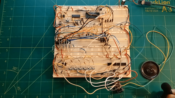
It’s technically true that any piece of software can be reproduced in hardware, although modern software’s size and complexity generally makes this a non-starter. But if we go far enough back in time, older software becomes easier and easier to implement in hardware. The original DOOM from 1993 might one day be recreated in full this way, but that day is not today. Instead, [Nick] has recreated the original music from that game, playing the opening track in nothing but 555 timers.

The circuit starts with a 555 timer that acts as a system clock with a rate of just over 7 Hz. These pulses feed a binary counter which in turn feeds a decoder, giving the circuit 15 positions. Each output of the decoder feeds to a diode matrix which stores information about what pitch the circuit should play. The circuit only needs to play six pitches so the diodes effectively connect each moment in time to one of these six notes. From there the circuit feeds into a set of switches which select different resistor networks of another 555 which is actually responsible for producing sound. The resistor networks have different values to adjust the timing of the 555 to produce different pitches.

Of course this entire exercise is largely academic as almost any microcontroller would be able to be programmed to play this chiptune quite easily, but it’s not a bad idea to get down into the weeds of digital logic from time to time in order to refine one’s skills and knowledge about what’s really going on in the inner workings of circuits. Or, go even deeper than that and build the logic gates themselves from first principles.
Continue reading “DOOM Played On Series Of 555 Timers”

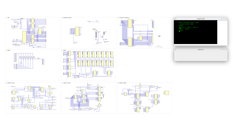
A view of the schematics for each major component.

Simulating The Commodore PET

Over on his blog our hacker [cpt_tom] shows us how to simulate the hardware for a Commodore PET. Two of them in fact, one with static RAM and the other with dynamic RAM.

This project is serious business. The simulation environment used is Digital. Digital is a digital logic designer and circuit simulator designed for educational purposes. It’s a Java program that runs under the JVM. It deals in .dig files which are XML files that represent the details of the simulated hardware components. You don’t need to write the XML files by hand, there is a GUI for that. Continue reading “Simulating The Commodore PET”

Image

Virtual Nodes, Real Waves: A Colpitts Walkthrough

If you’ve ever fumbled through circuit simulation and ended up with a flatline instead of a sine wave, this video from [saisri] might just be the fix. In this walkthrough she demonstrates simulating a Colpitts oscillator using NI Multisim 14.3 – a deceptively simple analog circuit known for generating stable sine waves. Her video not only shows how to place and wire components, but it demonstrates why precision matters, even in virtual space.

You’ll notice the emphasis on wiring accuracy at multi-node junctions, something many tutorials skim over. [saisri] points out that a single misconnected node in Multisim can cause the circuit to output zilch. She guides viewers step-by-step, starting with component selection via the “Place > Components” dialog, through to running the simulation and interpreting the sine wave output on Channel A. The manual included at the end of the video is a neat bonus, bundling theory, waveform visuals, and circuit diagrams into one handy PDF.

If you’re into precision hacking, retro analogue joy, or just love watching a sine wave bloom onscreen, this is worth your time. You can watch the original video here.

Continue reading “Virtual Nodes, Real Waves: A Colpitts Walkthrough”

Image

70 DIY Synths On One Webpage

If you want to dip your toes into the deep, deep water of synth DIY but don’t know where to start, [Atarity] has just the resource for you. He’s compiled a list of 70 wonderful DIY synth and noise-making projects and put them all in one place. And as connoisseurs of the bleepy-bloopy ourselves, we can vouch for his choices here.

The collection runs the gamut from [Ray Wilson]’s “Music From Outer Space” analog oddities, through faithful recreations like Adafruit’s XOXBOX, and on to more modern synths powered by simple microcontrollers or even entire embedded Linux devices. Alongside the links to the original projects, there is also an estimate of the difficulty level, and a handy demo video for every example we tried out.

Our only self-serving complaint is that it’s a little bit light on the Logic Noise / CMOS-abuse side of synth hacking, but there are tons of other non-traditional noisemakers, sound manglers, and a good dose of musically useful devices here. Pick one, and get to work!

Image

Custom Hat Gives Vintage Mitutoyo Calipers A New Lease On Life

Metrology fans are usually at least a little bit in love with Mitutoyo, and rightfully so. The Japanese company has been making precision measuring instruments for the better part of 100 years, and users appreciate their precision almost as much as the silky smooth feel of their tools. If you can afford it, a Mitutoyo caliper is quite an addition to your toolbox.

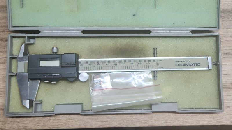
As good as they are, though, they’re not perfect, which is what led to this clever Mitutoyo digital caliper hack by [turbanedengineer]. The calipers in question, a digital set from the early 1980s, happen to have a unique history with a tangential Hackaday angle — they belonged to [Dhaval], mechanical engineer and avid motorcyclist who happens to be the late elder brother of our own [Anool Mahidharia].

The tool, in need of a little TLC, made its way to [turbanedengineer] who first restored the broken battery contacts. Once powered up again, it became apparent that while the caliper’s native metric measurements were spot on, the internal conversion to inches was considerably off. This led [turbanedengineer] to the data port on the tool, which is intended to send serial data to an external computer for logging measurements. After a little experimentation to nail down the data format, he prototyped a tiny circuit using an ATtiny85 and an OLED display that reads the caliper data, converts metric to inches, and displays both measurements on the screen. The prototype led to a more permanent version, which cleverly sits over the original display and taps into the data port without any free wires. The video below shows the very slick results.

Our hearts go out to [Anool] and his family for their loss, and we tip our hats to [turbanedengineer] for his thoughtful and respectful hack of a storied tool. We know that anthropomorphizing tools makes no rational sense, but we think it’s safe to say that a tool like this has a soul, and it’s probably happy to be back in the game.

Continue reading “Custom Hat Gives Vintage Mitutoyo Calipers A New Lease On Life”

Image

A Super-Simple Standalone WSPR Beacon

We’ve said it before and we’ll say it again: being able to build your own radios is the best thing about being an amateur radio operator. Especially low-power transmitters; there’s just something about having the know-how to put something on the air that’ll reach across the planet on a power budget measured in milliwatts.

This standalone WSPR beacon is a perfect example. If you haven’t been following along, WSPR stands for “weak-signal propagation reporter,” and it’s a digital mode geared for exploring propagation that uses special DSP algorithms to decode signals that are far, far down into the weeds; signal-to-noise ratios of -28 dBm are possible with WSPR.

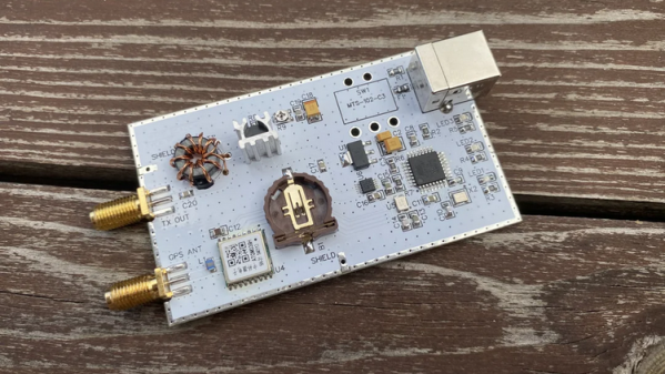
Because of the digital nature of WSPR encoding and the low-power nature of the mode, [IgrikXD] chose to build a standalone WSPR beacon around an ATMega328. The indispensable Si5351 programmable clock generator forms the RF oscillator, the output of which is amplified by a single JFET transistor. Because timing is everything in the WSPR protocol, the beacon also sports a GPS receiver, ensuring that signals are sent only and exactly on the even-numbered minutes. This is a nice touch and one that our similar but simpler WSPR beacon lacked.

This beacon had us beat on performance, too. [IgrikXD] managed to hit Texas and Colorado from the edge of the North Sea on several bands, which isn’t too shabby at all with a fraction of a watt.

Thanks to [STR-Alorman] for the tip.

[via r/amateurradio]

Image

Clock Mixes Analog, Digital, Retrograde Displays

Unique clocks are a mainstay around here, and while plenty are “human readable” without any instruction, there are a few that take a bit of practice before someone can glean the current time from them. Word clocks are perhaps on the easier side of non-traditional displays but at the other end are binary clocks or even things like QR code clocks. To get the best of both worlds, though, multiple clock faces can be combined into one large display like this clock build from [imitche3].

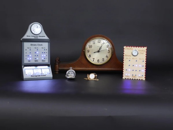
The clock is actually three clocks in one. The first was inspired by a binary clock originally found in a kit, which has separate binary “digits” for hour, minute, and second and retains the MAX 7219 LED controller driving the display. A standard analog clock rests at the top, and a third clock called a retrograde clock sits at the bottom with three voltmeters that read out the time in steps. Everything is controlled by an Arduino Nano with the reliable DS3231 keeping track of time. The case can be laser-cut or 3D printed and [imitche3] has provided schematics for both options.

As far as clocks builds go, we always appreciate something which can be used to tell the time without needing any legends, codes, or specialized knowledge. Of course, if you want to take a more complex or difficult clock face some of the ones we’re partial to are this QR code clock which needs a piece of hardware to tell the time that probably already has its own clock on it.