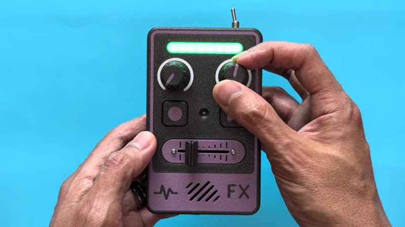
[Adafruit]’s Voicebox FX gadget is a fun, well-documented project that serves another useful purpose: being a fantastic reference design for audio on CircuitPython, with I2S audio components. Be sure to check it out if you have a project that involves any of that and could use a few pointers, or if you just want to jog a few ideas loose.
I2S (Inter-IC Sound) is a protocol aimed squarely at moving audio data between components as digital signals. Our own [Jenny List] can tell you everything you need to know about I2S. It’s a relatively simple interface that is not at all fussy about actually being used for audio, and that has led to it being put to some unusual uses.
The Voicebox FX uses an I2S microphone, an I2S amplifier, and an RP2350 microcontroller to record and play sound as well as offer a variety of effects controlled by physical inputs. It’s all wrapped up in a slick 3D printed case, and while it’s a fantastic reference design, it looks like a fun toy in its own right.
Printed footwear is an intriguing idea, but as far as projects go it is somewhat more complex than it first appears. This guide to 3D printing your own clogs not only provides a solid process, but also acts as a list of the challenges and pitfalls involved. After all, a piece of footwear is actually a fairly large object. Failed prints can be costly and time-consuming, so a guide like this is a valuable resource.
First of all, a 3D printer that can handle multi-material printing is called for. The footwear itself will be printed in TPU 90A as a sweet spot for hardness, but the print will require supports and those supports will need to peel away cleanly. The solution is a shoe printed in TPU with a rigid support structure of PLA. Using two different materials in the same print with anything remotely resembling efficiency calls for either a dual-nozzle print head, or a multi-toolhead printer.
3D printing one’s own clogs can be rewarding, if not necessarily cost-effective.
Here we want to take a moment and say that while the guide itself suggests PETG is also a suitable support structure, we suspect this might only be true for the exact filament formulations used in the guide. The safer approach is to use PLA. Why? As we’ve seen in other tests, PETG has been observed to stick extremely well to flex filaments in general, whereas PLA doesn’t really want to stick to anything other than PLA. The exact formulations of TPU and PETG used in the guide might be compatible with one another, but in general we recommend sticking to PLA as a rigid support for flexible filament.
Assuming a capable printer and suitable materials are nailed down, one also needs to worry about keeping the TPU dry. It is very sensitive to moisture, which directly affects print quality. You’ll also need to dial in the settings — a gyroid-patterned infill of 15% provides the right amount of “squish”, which is most effectively fine-tuned by changing the infill pattern rather than the density.
Is it worth the time and effort and filament cost to print one’s own pair of slip-ons versus simply buying a pair of Crocs®? Maybe not, but it can still be rewarding and this guide will help minimize any failed prints in the process. And if you do get a nice print but the TPU is sticking a little too well to the build plate, reach for the isopropyl alcohol.
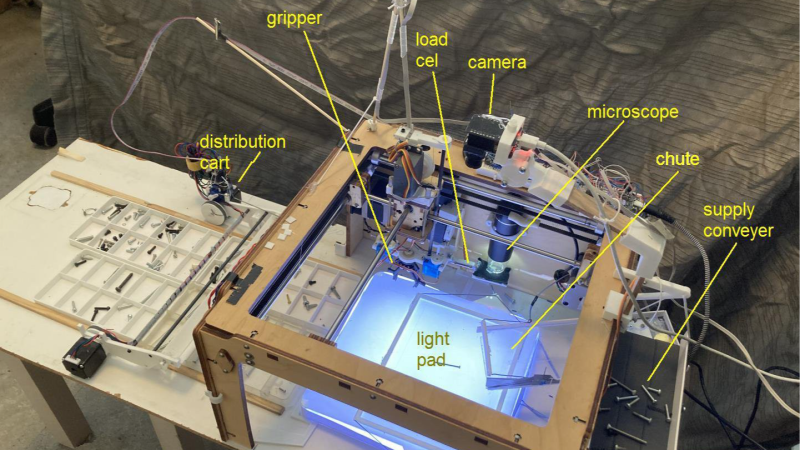
As someone who disassembles and repairs hardware, [Aad] eventually ended up with a huge collection of mixed bolts and screws. This led to creating the automatic bolt and screw sorting system you see here, although in a way it is just a proof of concept. Bolts and screws happen to be a useful application for now, but the system is capable of sorting just about any small objects.
A bit of machine vision detects the size and shape of each object. Weight can also be measured.
Mixed pieces go onto a large conveyor belt, shown on the right. This feeds a few screws at a time down a chute, where they roll onto an illuminated platform.
Above the lit platform is a camera, and machine vision is used to detect the size and shape and orientation of each screw. A robotic gripper on a gantry picks the screws up one by one — separating them first if they happened to clump together — and places each in a drop-off cart. The cart drops the object into a receptacle with its brethren, making sure similar ones are grouped together. Watch it in action in the video, embedded below the page break.
It’s a great build that shows fancy components aren’t necessary for good results. Servos and steppers are controlled with an ESP32-WROOM board, and a piezo sensor detects screws falling off the conveyor. Some of you may have noticed a repurposed Ultimaker 3D printer serving as the bulk of the system, its hot end having been replaced with a gripper that can raise and lower. The overhead camera is an ESP32-CAM adapted to accept M12 lenses so it can focus on the platform.
There’s one more feature worth mentioning — the system also has the ability to measure the weight of a picked object by placing it onto a moveable inspection platform, which can optionally put it under a USB microscope for a closer look. Everything is controlled by a nearby PC, so there’s a lot of flexibility built into the system.
We suppose that once all the screws and bolts in a shop are sorted, it only makes sense to sort all the nuts. Are there other objects besides screws and bolts that would be useful to sort with a system like this? If you have any ideas, don’t keep them to yourself! [Aad] would love to hear your comments and ideas, so share them below.
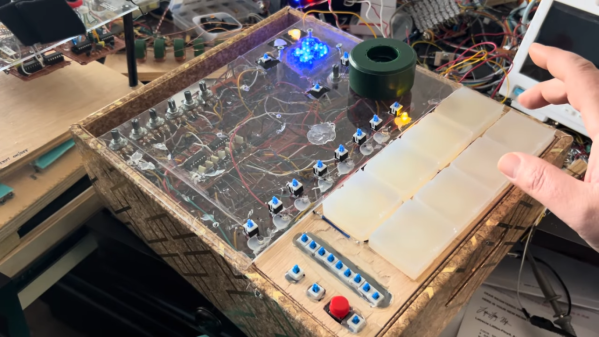
A little over a month ago, we featured a project from [Igor] who built 64 bits of DRAM from scratch using discrete components. Jokes about memory pricing aside, he did have a use case for such a small amount of memory — he is using it in a custom-built drum machine. But featuring the memory build and not the drum machine was perhaps putting the cart before the horse, so in this video, [Igor] shows off the construction of each part of his impressive 16- or 64-step sequence drum machine.
This isn’t Igor’s first drum machine, either, although his previous build was a bit more limited. It had fewer steps in the sequence and didn’t quite have the range of his newer model. The upgraded version can play more steps but also includes force-sensitive drum pads based on piezo sensors and more voices (drums) as well. Each voice is built electronically using various op-amps and passive components, and [Igor] has the schematics for each of them, as well as every other part of the drum machine, for those looking to recreate any part of this on their own. There’s a lot going on in this lengthy video as well, so for the musically inclined, it’s worth taking a look in full.
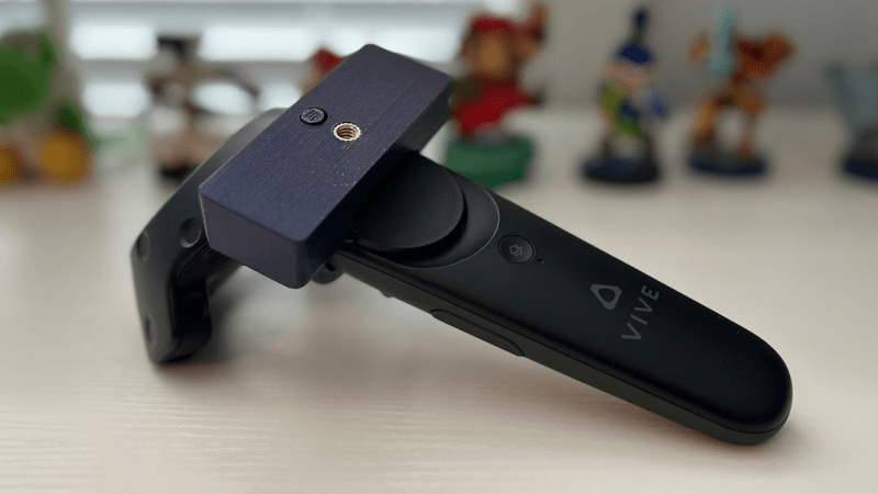
Full body tracking in VR applications involves attaching sensors to one’s body, and [Jaki] has a DIY method to do it on the cheap: the Vive Tracker Lite project repurposes Vive controllers as lighthouse-based trackers, no hardware modifications required.
A common method of doing body tracking is to strap on some Vive trackers. Those are extremely hacker-friendly pieces of hardware, but [Jaki] observed that older Vive VR controllers can be had for cheap, and already contain everything a tracker needs. Some new firmware and a custom mount is all it takes to turn them into perfectly usable body trackers.
But what about a wireless receiver? [Jaki] has that covered as well with the $5 Viva Dongle, which uses a Pro Micro NRF52840 to act as a cheap DIY alternative to the official dongle hardware.
We appreciate the effort put into making this project accessible to everyone, even novices. [Jaki]’s put effort into a Python program with a full GUI to make the flashing of firmware as easy as possible for both projects. Experimenting with body tracking in VRChat or games with mods is just some recycled hardware away.
Granted, a Vive controller is not the slimmest piece of hardware, but all it takes is a firmware change and a 3D-printed fixture to make a perfectly serviceable tracker. That being said, we’re sure an enterprising hardware hacker may crack a controller open and embark on a serious rebuild, or even interface to some of the inputs in a clever way. If you’ve done that or know of someone who has, drop us a note on our tips line because we’d love to see it.
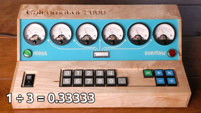
[lcamtuf] is not just a calculator superfan, but also a skilled builder. That much is evident in the fabulous design of Calcumator 2000, an electromechanical calculator that uses voltmeter readouts as digits (plus one at the bottom to represent decimal place). There are plenty of high-quality build images, so give it a look!
Meters like the one on the right (numbered 0 to 9) act as digit displays. The meter on the left indicates decimal position.
Calcumator 2000 is a bit of a love letter to a time when display technology hadn’t quite yet produced anything suitable for calculator use. This resulted in calculator designs that are generally unrecognizable compared to the 7-segment display based devices we see today. The Calcumator 2000, in all its electromechanical glory, would have fit right in that era.
The Calcumator 2000 has all the usual buttons one would expect from a simple calculator and drives a total of seven readouts, one of which acts as the decimal point. The idea of using voltmeters as digit displays came from [lcamtuf]’s voltmeter clock, an earlier work with a similar attention to detail in its design and assembly.
We want to take a moment to admire how clean the blue panel is. [lcamtuf] made it by painting one side of an acrylic panel, cutting the letters and design out on a CNC mill, then filling with white paint. The depth of the cuts gives the white elements a nifty multi-layer effect that really complements the design.
Want to see it work? Oh yes, you do. Check out the video, embedded just below.
It’s never been easier to get a printed circuit board made. In fact, almost every electronics video out on the internet will incessantly remind you of this fact now. But making a custom PCB wasn’t always as straightforward as sending a KiCad file to a board house. Many DIY methods involve harsh chemicals and tedious processes, but did have the potential benefit of taking much less time than waiting on boards to arrive in the mail. [Bettina Neumryr] is demonstrating one of these older methods, called the toner transfer method, using a circuit that was printed directly in an old magazine.
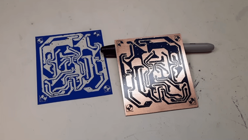
The first part of the toner transfer method is to create an image that can be printed. Since this circuit came from a magazine, it is first scanned in to a computer and imported into GIMP, where it can be scaled to match the size of the components and then sharpened to make a crisp print. With the image ready, it’s time to print the image onto some toner transfer paper, ensuring that the printer in question is a laser printer which actually uses toner. From there, a sheet of blank copper PCB is prepared and then the toner is transferred by heating, in this case using a laminator. After that its etched, removing all of the copper not protected by the toner, and then the toner itself can be removed which leaves behind the copper traces.
For those of you who were around when toner transfer was in vogue, this video might not have much value. But for anyone who can’t use a board manufacturer for whatever reason or is looking for alternatives, a modern video showing the method could be much more useful and have better context for beginners than videos made a decade or more ago now. Some of those older methods include similar processes using inkjet printers instead, but there are more modern DIY methods as well using lasers or CNC machines too.