The game has been released, and all of the subsequent bug fixes and patches have been rolled out. Lemonade Stand has actually been finished. There is tons of advice to be found online for what to do to make your first game. Most of it talks about the scope of your project, and most of it says to keep it small. I have talked about this before, but my original goals for Lemonade Stand were something of a paradox, in direct opposition to each other. I had wanted a project that was small enough in scale that I could actually finish it, but at the same time I wanted to test myself, to push the boundaries of what I was capable doing as a single developer.
The idea of lemonade stand seemingly fulfilled both of those goals. A business simulator would be the most complex thing I had programmed up to that point, involving lots of AI acting independently in a system, and yet the classic Lemonade Stand games seemed simple and manageable. I had started development with the intention of finishing in 6 months. From the day I started it ended up taking roughly 18 months. Lots of that is due to having a somewhat busy school schedule and other projects eating up lots of time. Lots of that is also due to lack of time management and scheduling, something I have learned a lot about over the course of this project. There were instances of time stretches up to 3 months long with no progress being made. Ultimately the reason Lemonade Stand was only ever released was because in the month preceding its initial launch date, I decided I was going to finish the game.
I made a conscious decision that this was it, this was the last stretch of development. For maybe a little more than 2 weeks I worked on the game almost constantly, and in that time I made as much progress as I had in maybe the previous year. All the things I did leading up to release included:
Design and implement the entire UI
Implement and create achievements
Create the tutorial
Add sound effects
Add music
Balancing and bug fixes
Implement donations through In App Purchases
Create the Google Play store page
For those 2 weeks of actually working on the game I realized, I really could have done this at almost any time in the last year. And the game would have been finished that much sooner. For all my future projects, I will remember this experience and hopefully use it to be more motivated to do things with purpose and focus.
I think something that would help immensely is establishing goals. For the 2 weeks leading up to release I had a very clear goal of actually finishing the game, it was very tangible and felt very possible. However, I didn’t just keep this idea of finally completing the game hovering in my mind for motivation. I have a whiteboard hanging above my desk. On the whiteboard, I wrote a list of everything I had to do in the game for it to be done. It contained all the above bullet points almost word for word, but it also further broke down the tasks. Under designing the UI I wrote every single menu screen I would have to design and code. Under sound effects I wrote for what actions I wanted a sound for, under achievements I included implementing detection and rewards and adding the menu screen separately. Once I completed a task, I didn’t erase it, I crossed it out. Over the course of the two weeks every task I completed was on the whiteboard, and some new ones were added. On release day, with everything crossed out, I finally erased it.
In the future I will be doing pretty much exactly this for all of my projects. At most I’ll take it month by month, and establish not only tasks that I am going to complete today or better yet, right now, but also the longer term goals and checkpoints. I think doing this helps you get a sense of real progress while simultaneously ensuring you will never be at a loss for what to work on next. The sense of achievement and progress by physically crossing out each task, and seeing everything you have crossed out helps motivation too, and you can imagine the immense satisfaction from erasing the whiteboard.
While development of Lemonade Stand is currently complete, I will be putting blog post updates on hiatus, though there are a few areas of Lemonade Stand development I may return here to expand upon later. Until then, see you in the next update!
And we’re back with the next riveting installment of The Graphics of Lemonade Stand! Today I’m going to talk about a major issue I came across while creating the art and levels of my little lemonade game, that being losing sight of the art style I wanted to capture. When I set out to make Lemonade Stand I wanted a project that was both bigger than anything I had previously tried to make but also something that I could actually finish. The first part of that wish was pretty stupid seeing as this is going to be the first project which fulfills the second wish: actually being completed. Despite my somewhat conflicting ambitions, the art style was mostly informed by the goal of actually finishing the game so I wanted to keep it as simple as possible. I fell onto the charming voxel style blocky graphics of other mobile hits like smashy road, crossy road, floppy road, and others of that verb-y road ilk. The soft, almost pastel colors complimented by the hard, almost completely rectangular geometry seemed like something that was easy enough for me to grasp. And it was even proven to be popular with the masses! Unfortunately I initially failed miserably. My first vain attempts at capturing that charm fell short of the mark, and you will be able to see it in the complete game, because I’m not changing them. My failure stems from a couple of things, and I’ll go into what I believe to be the two most important ones.
Failure to Define a Level Design Process
The thing that dominates the art style I was going for was simplicity. The thing about simplicity is it requires a lot of work to look like not a lot of work, it requires foresight and planning. I did none of that. Firstly I went at the subtle art of level design by mostly completely ignoring everything I had ever thought or learned about the practice and just kinda making what I thought would look good. This was perhaps just shy of attempting to paint a beautiful canvas with a chainsaw dipped in paint, but for the first two levels I made it produced results. Slightly incoherent and noisy results, but I wasn’t looking for perfection, I was looking to finish this dumb game. Those two levels were the park level and the beach level. You can see them below.
If you couldn’t tell this one is the parkAnd this one is the beach
I’ll start by picking on the park here, which is essentially a meaningless maze. The path structure makes no real sense other than looking complex which isn’t really a good thing. I think I mostly wanted to test my pathfinding and collision avoidance systems when I arbitrarily decided to make the paths. For all the random trees and shrubs I put everywhere, it was just to fill the empty space when they could have been arranged more naturally. This was the first level I made and before I had completely defined my workflow, so perhaps some leniency may be granted but its still a poor example. Overall the level lacks composition, which a static level should have plenty of, and there is practically no color diversity, everything is just green. This might help create some contrast with the relatively bright colored walkers but overall it makes the level boring to look at. I only used image sources for making the bench and swing set, everything else was just made up and random. What I should have done was:
Define a color palette
Look at image sources to get a feel for how a real space would be laid out
Define the general flow of walkers
Use composition techniques to highlight the lemonade stand itself with things like guiding lines and the rule of thirds
Build the paths based on the previous three points
Add objects while preserving and highlighting negative space to emphasize the lemonade stand
Eventually by maybe the last 2 levels I was doing some of these things but the thing I never did was the first and most important part for the art style: defining a color palette. Remember how the soft inviting colors were one of the two defining characteristics of the art style I wanted to capture, and here I basically threw it all away. Instead of taking the time to plan a level design process I mindlessly set about creating a level, and the art style suffered because of that. Unstructured progress is almost as bad as no progress.
Over reliance on Image Sources
Now onto my second failure that I did in part to try to make up for the first. Realizing I wasn’t making levels that were grounded in reality I tried to fix that for my third level, the town. This is by far my worst one.
It suffers from some of the same problems as the first two levels, not enough color diversity, over usage of objects to fight negative space, but at least its layout kind of makes sense. Its like a little town square! That’s because I took inspiration from a real town in the Songjiang District in China. It looks like this:
Confused? Good. Welcome to Thames Town. What is a British Market town doing in China you ask? Who freaking knows, you can read about it here and oggle at the same pictures that I base the town level off of here. Anyways, pretty fascinating place isn’t it? Unfortunately I might have became too inspired by the quaint town and based my level off of it way too much. I was trying to apply the minimalist blocky style of graphics and bright pastel colors to this dreary and geometrically complex location, and the two didn’t match. Instead of using the elements of the town to inform the design of my level, using just enough geometry to suggest the style of building I wanted, I created the building I wanted and applied the art style like a coat of paint. That is not at all how level design should work.
This reliance on one image source made me realize something I think is incredibly important, and something I will be using for every single project in the future. You should always use two different types of image sources. One of the thing you are trying to make, and one of the art style you are making it in. Your goal should be to focus on the second source and use the first to inform how you add things within your art style. This will ensure that you never lose sight of the art direction like I did, and ensure consistency across all your levels or assets or whatevers.
Improving
After seeing the failure of my previous three levels I decided to actually try and make two somewhat decent levels. I defined a level creation process and used two different types of image sources, and I came up with the suburbs and the city.
I think these two levels are better enough than the first three to warrant being set apart. I mean I feel as though there was a noticeable improvement. But enough of this subjective nonsense, let me tell you a few of the key things I think helped me focus my art direction. First of all was, use geometry for everything. In the beach level and the town level I was trying to get fancy with materials and procedural textures to created the window panes and waves and all this nonsense. None of it fit within the art style I wanted. So for the second two levels I only used solid colors like I should have from the beginning. Also, this is a more of a technical issue than anything else, but my rendering settings were way too low. I cranked up the number of samples to 100 to get rid of the ugly shadows. Lastly, while I didn’t create a color palette like I should have, I did emphasize using softer pastel colors for the buildings and tried using color contrast to draw the eye towards where the stand could be located. While the last two levels are by no means works of great art I still think they’re better than the first three. Now its really onto the making the UI of the game not suck, see you in the next update!
We’re back with a long overdue update on Lemonade Stand. A while ago I had completed the first phase of development, the game was feature complete, and all I had left to do was create the levels and tidy up the user interface and I was practically done! Well as it turns out actually creating the content on top of the game systems was also going to be a lengthy task. Who would have guessed. Now, however, that phase of development is also finished and I’m here to tell you how it went and also maybe give you a couple of tips and relate some things I learned throughout the process, things primarily about productivity and the asset creation pipeline.
Workflow Development
My art creation workflow came out of the combination of 3 things: the software and techniques that I was comfortable working with or wanted to expand upon, the art style I had in mind for the game, and the limitations that my platform and code imposed upon me. I have lots of prior experience working with Photoshop and as much as I love open source and free alternatives in my mind it is an irreplaceable tool, so I knew I would be making good use of that. Also I had some previous experience working with Blender, which is probably my favorite software ever, and I wanted to expand on my 3d modelling skills. Also, I knew I wanted to write all the code of this game myself and I was working in native android, so there was no way I was going to be making a full scale 3d game engine as that was way beyond the scope of my project. That’s where I decided to use 3d renders to give the game a faux style of low poly voxel art that has been incredibly common among mobile apps lately. That’s also where the art style informed my workflow, to capture the 3d style I wanted I would have to emulate it in 2d so that affected the way I rendered and processed each image in Photoshop.
Level Creation Workflow
Rather than rendering every tile onscreen individually I would create a “background” for the level that had as much detail as I could put in with the knowledge that anything I placed that might appear in front of one of the walkers would have to be later processed by the rendering code I wrote. This allowed the game to be more efficient and gave me more creative freedom in creating the environments, and I think it helped me work faster. Instead of having to visualize the level as a combination of tiles I could create the entire level at once. I created a few tiles consisting of things like trees or lamps that would regularly appear in places that walkers could walk around so I could easily add them in through the tilemap, but initially I created the level as I wanted it to appear in Blender. Later I would split the scene into 3 layers, the “background” was layer one and the first rendered image that would be behind everything else in the level. This was the image with the most detail to increase efficiency. Then I would have layer 2 be all the trees or lamps that would need to actually be rendered in the game engine so walkers could appear in front or behind them. And finally I separated the layer of “scenery” the things that would always be in front of the walkers and obscure your vision of them. MY workflow ultimately evolved to look like this:
Create the entire level in blender from an isometric perspective
Split the level into 3 layers, the background, obstacles, and scenery
Render the background and scenery layers and export them into Photoshop for editing
Create the tileset defining walker’s paths, spawn points, and obstacles
Mix all the ingredients in their corresponding layers and now you have a level!
This slideshow requires JavaScript.
I would create images for all the obstacles to be reused in each level so I only used the second layer in blender to tell me where to put the obstacles in the tilemap, it never actually got rendered. In Photoshop I would usually only edit the shadows to make sure there weren’t any sharp cutoffs and to resize the images so they had the correct scale. I was able to make my 5 levels I’m shipping with very quickly once I got this workflow down. I think that’s the most important lesson, is once you have defined a clear workflow you should stick to it for the remainder of the project to actually be able to finish. And the 3 things which usually define your workflow are your abilities and experiences (or goals), the art style and direction of the project, and the technological limitations you face.
Animations Workflow
For making animated assets the workflow was a little different, but it still followed the general idea of creating everything in blender then using Photoshop to convert the assets into a 2d form. I decided to use spritesheets, while a somewhat antiquated animation format I have lots of experience with them and decided to use it. When I say I used spritesheets, I mean that was the format I saved the animations to, I actually animated the walkers using bones in blender and then exported each frame as an image. I then used Photoshop’s awesome animation and scripting features to convert the frames into a spritesheet with a set amount of rows and size. I made use of this handy script to convert layers into a spritesheet, and used the “load files into stack” option to load each file into a layer of a single image.
Also I used the “actions” feature to crop or resize or even edit the shadows of each frame automatically in Photoshop. This handy tool lets you record any action or combination of actions in photoshop, from applying the eraser, a brightness or contrast layer, or cropping and resizing the image, and apply those actions automatically to a batch of files. After that the spritesheet was ready for production.
This is my new favorite tool
Lastly I want to make one thing clear: I am by no means a professional artist or even a professional game developer by any stretch of the imagination, so my specific workflow probably isn’t the best and you probably shouldn’t try to copy it exactly. Despite this, I feel the broader points I made, about what your workflow should be defined by and sticking to it throughout the project, are very important for your productivity. If your game ever wants to see release then adhering to structured progress will be the best way to get there. With that said, now Lemonade Stand enters the next stage of development: making the UI not suck. Until then, see you next update!
Before reading about this specific way to bring fpv to your hubsan quadcopter, I must warn you: Do not actually do this! There are other far better ways to accomplish this exact same mod requiring less money, less work, and less time. In fact I detailed one of these options in part one of this duology of quadcopter modifications, so if you want to do something like this then follow that guide. This update is really just something of a warning about my first failed attempt at modding my hubsan drone.
Initially I had the idea to use the onboard camera included in the hubsan x4 h107c model, after scouring the internet for days on end I came across this picture showing that the camera’s circuit board did in fact have a video out which presumably could be hooked up to a video transmitter.
Here you can see the fourth point is video out. I was hoping to cut down on the added weight by making use of the camera already on the quadcopter, which seemed reasonable enough. Next up, I needed a transmitter, and I selected a 200mW micro VTX, specifically the TX5823. Here was where I ran into some problems.
Of course it wouldn’t be that simple
A couple of things are wrong with this setup. First off, the transmitter is running on the same power and on the same circuit as the brushed motors of the quadcopter. These motors create lots of interference when under a heavy load, which is essentially all the time when you’re flying. Second, though you can’t see it in the image, the antenna’s shell was not grounded. The latter of these was an easy solution luckily.
Previously I had only connected the silvery core of the antenna to the proper part of the transmitter, but as it turns out you also need to ground the outer shell. Separating the antenna was a little tricky but doable with some wire cutters. After I re-soldered it, the connection was much more secure, though I still used hot glue to hold the antenna in place.
Here you can see the three connections. With the antenna problem quickly resolved, I was able to actually test the transmitter and lo and behold it appeared to work!
That false sense of completion so quickly stripped away
Testing the machine before putting it all back together and hot gluing everything for good measure. I thought I was done here, however as it turns out I still hadn’t escaped the interference caused by the brushed motors. When I reassembled the quadcopter’s frame and tried to take off, I was immediately met with static. Never try to fly in a snowstorm.
After further research I thought I found a solution in the pololu 3.3V voltage regulator. I found similar mods posted on the internet saying they made use of it, so I decided to give it a shot as well. Unfortunately it didn’t work out for me.
Its always Christmas time
The voltage regulator supposedly would filter out interference caused by the motors and supply a constant 3.3V, however for me I was met with an even layer of static. While the video feed wouldn’t become entirely white noise when flying, the quality was still far too grainy to fly with.
A closeup on the failed efforts
Despite this mod attempt ultimately being a failure, I still feel like I learned a lot about FPV equipment and got to stretch my soldering skills, so I wouldn’t rule the experience a complete loss. I will most certainly be making use of my spare transmitter in a future build, so see you then!
I’ve had my trusty Hubsan x4 H107C for quite a while now, and had gotten pretty decent at line of sight flying. However, to better practice for eventually building my own FPV racing drone, I wanted to try to cheaply add FPV capability so I wouldn’t have to start learning all over again for flying in First Person View. This project took much longer than anticipated due to having to order additional parts, and then ultimately having to start over from scratch. In Part 1 I’ll do a rundown on what actually worked and what I should’ve done in the first place, with part 2 being a chronicle of my failure in case you want to see what didn’t work.
Part List
Doing this mod will be a very inexpensive way to try out and learn about drones, quadcopters, and FPV flying, so if you are thinking about getting into the hobby its not a bad way to go. Here’s everything I used to get up and running.
These three items will give you everything you need to get an fully capable FPV quadcopter up and running for only $150, normally the quadcopter itself would cost at least that much. As for tools for completing the mod you’ll need:
Soldering Iron
Hot Glue Gun
Philips #0 Screwdriver
Modifications
Installing the camera is a relatively simple process, first you need to open up the Hubsan’s shell with the screwdriver and a little bit of force. The two screws holding it together are on the underside of the quad, as shown here:
Disassembly images courtesy of the fantastic blog, Robotic Dreams
However before you try tearing the two halves of the shell apart, first you need to pop off the legs where they attach to the motor mounts. This is supposedly a feature of the Hubsan frame where during a crash the legs will just pop out instead of breaking, so it might require a little force.
Seriously check out this guy’s stuff its pretty cool
Now the last thing to remember when separating the two halves is that there will be the camera’s power supply running from the camera on the bottom half of the frame to the control board on the top half, so be careful you don’t break it!
You can tell this picture is from me because of the much lower quality
This is what the drone looks like after opening the shell and removing the battery carriage, however for our purposes that is an unnecessary step. Now to draw your attention back to the two wires supplying power to the camera, as the points where they meet the control board are where we will solder our camera. First, just either remove or strip the micro jst connector on the end of the camera and after that just solder the wires as shown.
Lets leave the story behind the hot glue for part 2 of this update…
Be careful when soldering the camera onto the control board to not inadvertently remove some of the already existing connections like the battery or recording camera wires. That’s really the trickiest part to this mod. Now that you’ve confirmed the camera is hooked up correctly just put everything back together the way you took it apart, leaving the camera outside the frame to be mounted on top. If you are unsure of your soldering job then a little hot glue can give it some permanence, however don’t use too much as you could block the battery carriage. Not that I’m speaking from experience or anything. The final step is to secure the camera to the top of the frame with your trusty hot glue gun, of course be careful to ensure you have enough wire on the camera to reach the optimal position, and not to use too much hot glue to add extra weight.
And that’s all you’ll need to get up and flying in FPV. You will likely have to adjust the trim and orientation of your hubsan as this will slightly change the center of gravity, but its a fair trade off to make considering the benefits. Once I get some what competent at flying the hubsan’s from the cockpit I’ll start work on a 3d printed micro quad of similar size to reuse this camera in it, so keep an eye out for that. In the more immediate future however, part 2 of this build log is coming soon!
The very last, and perhaps the trickiest feature I implemented in the game was a system that made it so the walkers wouldn’t walk into each other. This of course builds directly off of the system that allows walkers to follow a path, so you can refamiliarize yourself with that here and here. Now onto how this system actually works, essentially it boils down into 2 main steps, the first of which is an if statement that checks if the walker collides with another.
Step 1: See if the Walkers will Walk into Each Other
Obviously the entire goal of our system is to avoid this exact thing from happening, so we need to first somehow check if it is about to happen, then take a precautionary measure to avoid it. This might sound difficult to anticipate the action of two walkers, but its something real people do all the time, otherwise we would all walk into each other. Lucky for us, it turns out predicting the future in a controlled system is pretty easy. First we return to the code that handles all of the collisions with other walkers, where we check if their images are intersecting. This is done with a nested for loop, the outer one iterating through the array of walkers and the inner array checking to see if we are colliding with any of the other walkers in the array. That would be set up like this:
// First For loop, updating all the walkers
for (int i = 0; i <walkers.size(); i++)
{
    if (walkers.get(i).status == 1) // If the person is going somewhere
    {
        // The second for loop, to check if they collide with somebody
        for (int j = 0; j < walkers.size(); j++)
        {
            // If it is the same walker then move on
            if (j == i)
            {
                continue;
            }

            // If they collide with another walker
            if (collision(walkers.get(i), walkers.get(j)))
            {
                // Do stuff
The key realization here is at this stage we don’t know if they are going to walk into one another, essentially all we know is they are pretty close to each other. The next part of this process is making sure they actually are about to walk into one another, because even if their sprites are technically touching, they could be going in opposite directions or walking side by side. Luckily for us we know that all the walkers are following a path calculated by our pathfinding algorithm, we can use that to our advantage by seeing if the next step of the walker’s paths are the same.
// Make sure they have not just spawned
if (walkers.get(i).stepNum > 0 && walkers.get(j).stepNum > 0)
{
    // If they are walking into them
    if (walkers.get(i).path.getX(walkers.get(i).stepNum) == walkers.get(j).path.getX(walkers.get(j).stepNum) && walkers.get(i).path.getY(walkers.get(i).stepNum) == walkers.get(j).path.getY(walkers.get(j).stepNum))
    {
So that second if statement is very long. Essentially all it does is check if the x and y coordinates of the walker’s next steps are equal to each other, if so that means they are about to collide! The first if statement is a precautionary measure to make sure there will be a step in the walker’s path before this one because will be retracing their steps in part 3. Also all of the walker spawning happens off screen so any collisions won’t actually do anything! This entire system is mostly to make sure the walkers don’t look weird after all, so it doesn’t matter if we can’t see them! Though it also prevents odd bugs from multiple walkers buying lemonade at the time, but that’s beside the point. Now we know for sure there is going to be a collision, its time to stop it.
Step 2: Editing the Walker TileMap and Recalculating the Path
While I talked extensively about using and rendering tilemaps in this article, I didn’t mention that I also use another tilemap to save whether or not a walker can walk on any given tile. Essential it is a grid of numbers, which denote the spawn and despawn locations, as well as the passable and impassable tiles. This step is somewhat trivial but the most important part of the process of making the walkers avoid collisions. Essentailly we set the tile that the collision would happen on to an impassable tile, then recalculate the route to the walker’s destination. This is all done in only a few lines of code so I’ll go through it piece by piece.
// go around them by recalculating the path
startCoords = tileMap.coordsToTile(walkers.get(i).path.getX(walkers.get(i).stepNum - 1), walkers.get(i).path.getY(walkers.get(i).stepNum - 1));
badCoords = tileMap.coordsToTile(walkers.get(i).path.getX(walkers.get(i).stepNum), walkers.get(i).path.getY(walkers.get(i).stepNum));
targetCoords = tileMap.coordsToTile(walkerDeath.get(0).getX(), walkerDeath.get(0).getY());
tileMap.setTile(badCoords.getX(), badCoords.getY(), 0);
walkers.get(i).setPath(finder.findPath(walkers.get(i), startCoords.getX(), startCoords.getY(), targetCoords.getX(), targetCoords.getY()));
tileMap.setTile(badCoords.getX(), badCoords.getY(), 1);
We start out by creating 3 coordinate pairs. The first one is the previous step along our walker’s path which we will use as the starting place for our new path. The second pair is the tile that we would have had a collision on. The last coordinate pair is the walker’s destination, in this case the despawn point. Now we set the tile located at badCoords to 0 because that value makes the tile impassable. We then immediately recalculate the walker’s path with these new values, before immediately resetting the tile to its initial value of 1. Changing the value of this tile doesn’t cause any problems for other walkers because the tilemap is only considered when generating paths, and here we only create the path we need before resetting the tile. Because this article has been a little heavy on the reading side lets enjoy a nice long gif showing the fruits of our efforts.
Oh baby a triple… path recalculation
Here you can actually see I implemented all 4 directions of animation and added all the different colors of walkers, so they’re not just red anymore. You can also see how the walkers recalculate their paths so they walk side by side not once, not twice, but three times in one gif. Good stuff right there. Maybe next time they will actually buy lemonade at the stand instead of off to the left of it. I’ll see you in the next update!
Today I can officially say, after months of development and bug fixing that Lemonade Stand is finally feature complete. After today there are no more major features to be added, and no significant code to be written. I have not updated the site with articles covering every major feature yet, those are still on their way, but I thought I should at least write something to commemorate this milestone. I started this project this spring, with no previous experience in android development, and limited experience working with java in general. Above all this was a great learning experience, one that is by no means over and I look forward to continuing it. Before I delve into the future though, I’d like to at least take a look at all the features that are in the game. Without further ado:
Walker collision avoidance system (Article coming soon!)
Walker personality and AI system for buying/rating lemonade (Multiple Articles coming soon!)
So there you have it, a complete feature list. Some of these are kind of a given for this type of game like the inventory and weather systems, and because both are rather simple I don’t think they quite deserve entire articles to themselves. However I have already started drafting some articles for the personality generation of the walkers, the algorithm that determines if they are going to buy lemonade, and the collision avoidance system, so definitely expect at least 3 about those topics. It was actually the collision avoidance system that was giving me the most trouble in these recent weeks so I expect a write up on that will come soon. One very important topic not yet addressed is what I am planning to be the main game mechanic, changing the recipe of the lemonade as the game is running. This ties into the Walkers having random personalities so these topics will end up building on each other quite a bit. With the feature list covered, lets take a look at what lies ahead for the development of lemonade stand.
Now all the easy stuff is out of the way we can focus on the real interesting part of game development. In the spirit of making lists why don’t we make a list of things to do now to go along with the things we’ve done.
Add actual levels
Learn and implement good UI design
Fine tune difficulty and AI settings
Polish and Juice
In terms of creating content, I’m planning on making a few different levels and locales that will have different feels to them by editing the weather and walker AI. Implementing this in the code will be fairly trivial, in fact I already have the menu system prepared, so on that front the biggest time sink will be creating the graphics. I didn’t allow myself to work on any graphics until the codebase was complete, so now here we are.
For UI design up to this point everything has been default minimal effort, following the similar philosophy as working on graphics, I wanted to focus on learning and coding the java platform. I’ve also had little to no experience in designing UI and for a business simulator that’s kind of the most important part.
Fine tuning AI and difficulty is something that can only be done through rigorous testing. Once I have some levels implemented you can switch between I’ll have to make sure players don’t end up rolling in the cash after the first Monday, and that not every single person wants to buy lemonade etc.
Finally we get to the good stuff, my personal favorite part of game design. This is the part where you actually make the game good. If I implemented all the content, made the AI and difficulty reasonable, maybe I could say the game was done. However, the game would probably be pretty boring. There’s a saying in software development that goes:
The first 90 percent of the code accounts for the first 90 percent of the development time. The remaining 10 percent of the code accounts for the other 90 percent of the development time.
This is true for any software project, and especially so in games. Even if its not code I’m working on, the last 10% of the project will end up being likely not only as time consuming, but just as important as the other 90% of the project that’s already finished. This last 10% for my is going to be the polish and fine tuning that elevates the game from passable to actually good. In the AAA industry, you hear about games “going gold” all the time, meaning somewhat confusingly not that they’re surpassed an arbitrary amount of sales like in the music biz, but instead that the game is ready to ship, and they have started printing copies for retail. However nearly every single game also has a huge day one patch, containing what you hope is the remaining 10% and polish that will actually make the game you just preordered worth it. Or maybe its a last ditch effort to fix all the game breaking bugs that were rushed out the door, who knows. For Lemonade Stand, and all my future games, I hope to actually finish the game, including the polish before release. I hope you found this post somewhat interesting, I’ll see you in the next update!
Previously I Implemented the A* path finding algorithm so the people in Pineapple Town or wherever this game takes place can actually walk to wherever it is that they’re going. I was pretty excited about that, it was probably one of the more complex things to tackle in the making of this game and now I had finally finished it time for celebration! Well not quite. Actually all I had done was write the code to return a path for the Walker, as I dubbed the people trapped in my simulation, and now I needed to write the code for them to actually follow the path.
Following the Path
This wasn’t really that big of a deal, as you may remember from last time the final path returned is a series of locations for the walker to follow, and we can just generate a vector for the walker to travel along for each step of their path. That code ended up looking like this:
public void followPath()
{
    if (path == null)
    {
        System.out.println("path is null");
    }
    else // if a path exists then go to it step by step
    {
        dx = (path.getX(stepNum) - x);
        dy = ((path.getY(stepNum) - 72) - y);

        double factor = speed / Math.sqrt(dx * dx + dy * dy);

        dx *= factor;
        dy *= factor;

        // if they are at the next step check if its the end of the path and move up
        if (Math.abs(path.getX(stepNum) - x) < speed && Math.abs(path.getY(stepNum) - 72 - y) < speed)
        {
            setX(path.getX(stepNum));
            setY(path.getY(stepNum) - 72);
            dx = 0;
            dy = 0;

            stepNum++;
            if (stepNum == path.getLength())
            {
                status = 2;
            }
        }
    }
}
Here we set a static value for the walking speed of the walker, which is essentially how long it should take the walker to move from one step to the next. We divide that speed by the Pythagorean length of our travel vector to get a scalar value we can use to modify our total x and y distance that we move each frame. The checking if the path is null is really just a last resort to warn me something terrible has happened because there are other systems in place here to stop the null path from getting this far. The last if statement tells us the walker has reached the end of the path, and changing the walker’s status to 2 essentially just tells the walker to execute whatever they are supposed to be doing at the location they arrived at.
So that is how the walkers follow their paths. I went so far into detail about this because it is instrumental to understanding how they wait in line, as its a fairly simple modification to this.
Waiting in Line
For waiting in line I initially considered making the walkers recalculate their route to a predetermined “end of the line” tile which would change whenever it was occupied. But to me this sounded too complicated to implement, instead I decided to go for a more organic approach. Instead of artificially defining a line I would let how the walkers spawn and make their way to the lemonade stand dictate how the line forms. Lets look at the code and some game footage to get a better idea of what I mean.
if (stepNum == path.getLength() - 1)
{
    status = 2;
}

isWaitingLine = true;
The journey of our line starts here, if the walker’s destination is the lemonade stand then we check to see when he arrives at the step of the path before he starts buying lemonade. Once he is we then execute this code:
if (status == 3) // is waiting in line
{
placeInLine = path.getLength() - stepNum - 1;

if (isWaitingLine)
{
 dx = 0;
 dy = 0;
 if (walkForwards.getCurrentFrame() != 6)
 {
 walkForwards.update();
 }
}
We set this walker’s place in line relative to how many steps he has taken to get to the lemonade stand, giving priority to whoever is closest to the lemonade stand and then also whoever walked the furthest to get there. However, since this walker doesn’t have anyone else to deal with, he just keeps walking to the lemonade stand. So he enters status = 2 which will execute this code:
if (status == 2) // Arrived at end of path, is first in line
{
    dx = 0;
    dy = 0;

    if (wantsLemon)
    {
        inLine = true;
        placeInLine = 0;
    }
Now to see how our line develops we need to look at the collision code for when walkers walk into each other. Lets introduce a second walker to the situation.
if (collision(walkers.get(i), walkers.get(j), false))
{
    hasCollided = true;

    // if they are going to the lemonade stand
    if (walkers.get(i).wantsLemon)
    {
        // if they collide with somebody in line and we are not in line then get in line
        if (walkers.get(j).inLine)
        {
            // our walker is now in line, one place behind the person they collided with
            walkers.get(i).inLine = true;
            walkers.get(i).setStatus(3);
        }
Here we will say i is the new walker and j is the one who just arrived at the lemonade stand. We are checking if they collide with someone who is waiting in line, in this example our original walker who was just about to buy their lemonade. We tell our current walker that they are now in line and their place is defined by the code executed in status 3, the waiting in line status. So now we have two walkers who are next to eachother, they both want lemonade, and they are both technically “in line” and have placement to say who gets priority. Next we just tell the walker with the lowest priority to wait until all other walkers with higher priority leave, and that’s it! We’ve got a line going on.
else if (walkers.get(i).status == 3) // if the walker is in line
{
    // if they do not collide with somebody who is ahead of them in line then go forwards otherwise just hang out
    boolean hasCollidedNextPerson = false;

    for (int j = 0; j < walkers.size(); j++)
    {
        // If it is the same walker then move on
        if (j == i)
        {
            continue;
        }

        // if they collide with somebody ahead of them in line
        if (collision(walkers.get(i), walkers.get(j), false) && walkers.get(j).placeInLine < walkers.get(i).placeInLine)
        {
            hasCollidedNextPerson = true;
        }
    }

    // if they don't collide with anybody ahead of them in line and they are waiting then move up
    if (!hasCollidedNextPerson && walkers.get(i).isWaitingLine)
    {
        if (walkers.get(i).placeInLine != 0)
        {
            walkers.get(i).stepNum++;
        }
        walkers.get(i).isWaitingLine = false;
    }
Here we are manually advancing the step of the path that the walker follows when they meet no opposition from someone who is also in line and has a higher priority than them. This code may seem to jump around a lot but that’s because it takes advantage of 3 systems I already had in place for controlling AI, the collision system, path following system, and their “status” system. I think it was a good design decision to make use of those tools instead of creating an entirely new system to handle waiting in line. Now lets take a look at the code in action to confirm it does indeed work.
These walkers have realized that vehicles haven’t been implemented yet, and thus the street is safe to stand in.
I just spawned a few walkers and disabled buying anything to display the line forming. We can see that there is actually 2 lines forming here but that actually doesn’t provide any conflict as their place in line is not based on how many people are physically ahead of them but rather how close they are to the lemonade stand. Now lets wrap this up by finally looking at how I “implemented” the walkers cutting each other in line.
Emergent AI Behavior: Its a Feature not a Bug!
So something I quickly noticed when testing this code is that the walker’s don’t always let the person who has waited the longest go first, because their place in line is based only on their distance to the lemonade stand and how long it took them to get there. Instead of fixing this bug I decided to encourage this behavior ,cause you know what, in real life people don’t always let the person who waited the longest go first so why should my game do that! Call it a metaphor for the capitalist themes that Lemonade Stand is pushing, its survival of the fittest when you’re thirsty and the lemonade stand can only serve one person at a time. I accomplished this by addressing the edge case for when the walker encounters someone who has the same place in line as them:
else if (collision(walkers.get(i), walkers.get(j), false) && walkers.get(j).placeInLine == walkers.get(i).placeInLine)
{
    // if someone is in the same place in line as them let them cut you cause they're so mean
    walkers.get(i).placeInLine++;
}
So whoever we check first will end up letting the other person have the right of way. Technically in the code this means that its just this one guy being excessively nice but I like to think of it as him being taken advantaged of. Here’s some actual footage of this occurring:
What do you think those other two people are thinking as they watch this guy just stride in front of them?
I also made it so there is a delay when they buy lemonade, to make lines more likely to form. So really here I decided to change the code to favor a stylistic outcome that is probably not the “ideal” outcome you would initially expect. I think that this will add a lot to the game though, if the walkers only formed one line and always let the person first in line go that would perhaps look better, but I think this more organic system will help add character to the walkers. That is actually one of my primary goals for this game, and I think this was a good step to achieving it. Thanks for reading all the way through this marathon of an article, see you in the next update!
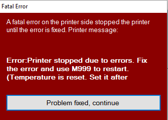
This week I was printing out a Recorder to add to my growing 3D Printed instrument collection when I was greeted with this very foreboding screen:
That’s a scary error message.
My 3D printer encountered a fatal error as the popup pointed out. Luckily the printer shut everything down or else something bad might have happened. This popup isn’t really very revealing about what that fatal error was however so I had to check the print log to see what exactly the error was. I was greeted with this:
The line is question is the second one: MINTEMP triggered ! Turns out the printer was reading the extruder temperature as zero degrees Celsius, not the temperature you want for melting plastic. So this meant that the failure occurred at either two parts of the temperature reading chain, either it was an issue with the electronics, either the RAMPS port or Arduino Mega analog circuitry was fried, or the thermistor itself was broken. The RAMPS port shorting out wouldn’t have been a big deal I could have used the other available port usually reserved for a second extruder and just switched it over in the firmware. However I was able to rule out an issue on the electronic’s side by attaching a 100k Ohm resistor to the RAMPS port and it got a reading of 20 degrees C. I was able to test because Thermistors are just resistors where the resistance reacts to the temperature, hence their name.
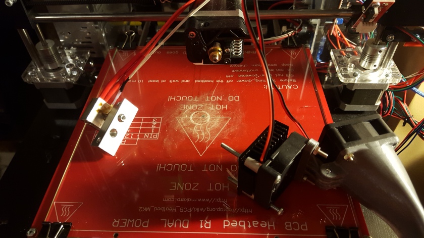
It was time to disassemble the extruder! I took off my cooling setup to be able to get at the nozzle, which is not a big deal at all, it only required removal of two screws.
Odd how only two screws hold this entire thing together.
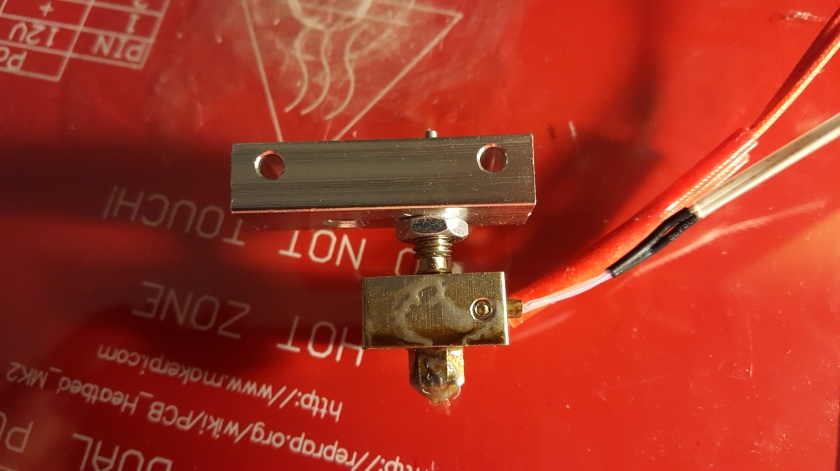
The thermistor is the white wires coming from the nozzle seen at the left. I was worried I might have to buy an whole new nozzle assembly but they are also very easy to remove, you only need to loosen a small hex screw on the side of the nozzle.
Don’t worry I cleaned the nozzle and heated bed very well after this.
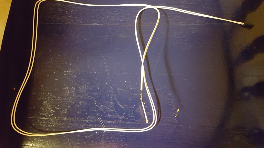
You can see the screw there keeping the thermistor in place. A visual inspection of the thermistor didn’t reveal much but testing it for resistance with my multimeter confirmed it was dead. Luckily for me, a replacement was only a 2 day amazon shipping away. I got a pack of five for 7 dollars which I’d consider pretty fair, especially if there’s any more failures like this.
I think the replacement’s wires have better sleeving anyways.
After installing the new one I was able to connect to the printer in Repetier without the red message of doom appearing, and it actually read the temperature accurately.
Its alive!
This update was a bit shorter than normal, probably because this repair didn’t take long at all. I’ll be back on track printing stuff now so we will hopefully see more developments in future updates. See you then!
In a previous article I mentioned how I had some issues with the way I decided to render isometric tiles, and implementing pathfinding. So lets talk about how it is I overcame those problems and why implementing A* was way more difficult then it should have been. First, so we are all on the same page, lets go over the A* algorithm itself.
The A* Algorithm
What A* is meant to do is find the shortest and most efficient path to get from point A to point B. Its important to make the distinction that not only is it the shortest as in the most direct path, but also the most efficient. The reason that this algorithm is so widespread is that it can adjust for both distance and efficiency.
This algorithm creates the best path by testing every node that is accessible to the object it is moving. In our case, a node can be a tile on a tile map. It tests every object for two values. First, its g cost which is usually the physical (or digital) distance that the mover would have to go to reach that node or tile. The second value it tests, is the node’s heuristic a value that estimates how cheap it is to go to that node. As an example, say you are racing in a dirt bike trying to escape from a bipedal amphibious radioactive monster. You come across a turn in a road that goes around a pit of quicksand. The shortest distance from point A to point B, that is, your current location to a nuclear bunker stocked with bipedal monster repellent, would be to cut across the muddy path. So your g cost tells you to keep going straight. However, the heuristic of the dirt road is way less than the heuristic of quicksand so the best path is to stay just on the edge of quicksand.
That’s what makes A* so convenient, it can be applied to myriad of situations and is (usually) not to hard to implement. Lets look at how we would go about implementing in java.
Implementation
A* works by keeping two sets or lists of nodes to check and compare their heuristic and g costs against each other. The first set is called the Open Set which contains all the nodes to be checked. Nodes are added to the open set based on if they are adjacent to either the starting position, or adjacent to a node in the closed set. Nodes are added to the closed set when their g cost and heuristic are calculated. The algorithm decides which nodes from the open set to check by defaulting to the one with the lowest combined g cost and heuristic. You can see how easy this would be to achieve in Java by using a SortedList for the open set and an ArrayList for the closed set. The open list is sorted by the combined g cost and heuristic of every node, the f value. However in order to populate the lists with nodes we need to define what exactly a node is.
private class Node implements Comparable<Node>
{
    private int x;
    private int y;
    private int cost;
    private float f;
    private float heuristic;
    private Node parent;
    private int depth;

    public Node(int x, int y)
    {
        this.x = x;
        this.y = y;
        f = cost + heuristic;
    }

    public int setParent(Node parent)
    {
        depth = parent.depth + 1;
        this.parent = parent;

        return depth;
    }

    public int compareTo(Node other)
    {
        if (f < other.f)
        {
            return -1;
        }
        else if (f > other.f)
        {
            return 1;
        }
        else
        {
            return 0;
        }
    }
}
So this is the creation of our node class, basically it is defined by its x and y values, which are taken from our level data array. Its other attributes are its ability to have a parent node, basically it saves the node that it is connected to so we can later recreate the pathway once the algorithm is done. Also it has a depth value, telling us how many levels we are within the algorithm and also the number of nodes that make up the path. Finally it can be compared to other nodes based on what its f value is, a prerequisite for being included in a SortedList.
Before going into how g cost and heuristics are calculated lets look at a visual representation of the algorithm using what we already know.
Image courtesy of Wikimedia Commons
Here we can see the open circles represent nodes in the open set while colored nodes are in the closed set. The more green the color is the closer to the goal the nodes are. Right away you can see how the algorithm investigates all the nodes in a straight line towards the goal until it hits a barrier, because those nodes all have much lower f values than the nodes way back by the starting position. Once it hits the barrier then it doubles back and investigates those nodes around the start.
Understanding nodes and the open and closed sets is all well and good, but how do we go about calculating the g cost and heuristic? Here is where it gets a little tricky. Lets start with the g cost.
// Get movement cost of node
public int getMovementCost(GameObject mover, int sx, int sy, int tx, int ty)
{
    CoordinatePair start = map.tileToCoords(sy, sx);
    CoordinatePair target = map.tileToCoords(ty, tx);
    int dx = Math.abs(target.getX() - start.getX());
    int dy = Math.abs(target.getY() - start.getY());

    if (dx != 0 && dy != 0)
    {
        return 108;
    }
    else
    {
        return 208;
    }
}
This function accepts the type of object that is being moved (in case you want a person and a car to behave differently), the starting x and y coordinates, and the target x and y coordinates. I convert the values from level data coordinates to actual x and y coordinates using my function I detailed in a previous article and then get the distance between the two point on the x and y axis. I then check if the mover is moving on more than one axis i.e. diagonally, and give it a lower movement cost than if the mover were to go directly up, down, left or right.
A crude illustration of the concept
This is to avoid people from walking in crazy zigzag patterns that don’t make any sense, which did happen a lot prior to fine tuning the movement cost of the two different types of moves.
We then calculate the heuristic by finding calculating the Euclidean distance between the node we are investigating and the goal.
// Get Heuristic of node
public int getHeuristicCost(GameObject mover, int x, int y, int tx, int ty)
{
    CoordinatePair start = map.tileToCoords(y, x);
    CoordinatePair target = map.tileToCoords(ty, tx);
    int dx = Math.abs(target.getX() - start.getX());
    int dy = Math.abs(target.getY() - start.getY());
    return (int) Math.sqrt((dx*dx)+(dy*dy));
}
An alternative to this is calculating Manhattan distance, essentially just adding the difference between the x and y positions of the two nodes without square rooting or squaring them. This would obviously be much faster, but does not work with the “zigzag” style system we are using to store our level data. This leads well into the next topic, the problems introduced by using zig zag style isometric rendering, which are not introduced when using “normal” style isometric data. More info can be found in the aforementioned previous article.
Problems with Isometric Data
As mentioned in the previous article, I am storing all my level data as an offset grid to better approximate how the level data will actually look in the game. An array of tiles might look like this:
While Manhattan distance works just fine with a standard grid, this offset data will not work at all with that distance calculation. This is because the tiles directly above the starting tile are actually either to the left or right of the starting tile, and not just above it. This is also why we needed to convert the coordinates of the nodes to actual pixel coordinates, because the cell coordinates of where the node is located in the array are inaccurate to where it is located on the screen. Essentially the need to convert the data slows down the algorithm with extra calculations.
Now to the issue that gave me the most trouble with implementing the A* algorithm into the zigzag data: selecting adjacent nodes to enter the open set. Lets start by looking at what we want to do, select the 8 nodes around the starting position.
Pretty colors
The green color denotes our starting position, while the red show the tiles with the smallest movement cost and the blue are the larger movement cost. You can immediately see a problem when looking at the coordinates shown on the image. If the algorithm simply added and subtracted 1 to the x and y location of the node, it would not get the right nodes at all. Instead the algorithm needs to take into account 5 different rows of data, with a different number of columns for each row. My solution to this is certainly not the cleanest but I couldn’t think of some kind of miracle equation that would give me all the correct adjacent tiles mathematically, so I had to iterate through each row individually. Here’s what the code looks like:
// Look at each tile neighboring our current one in a diamond pattern
for (int y = -2; y < 3; y++)
{
    // Check if y is odd to offset accordingly on the diagonal neighbors
    int offsetX;
    if ((current.y & 1) != 0)
    {
        // cellY is odd and y is odd
        offsetX = 1;
    }
    else
    {
        // cellY is even
        offsetX = 0;
    }

    // Make sure the diamond is wide enough in each row
    int numXNodes = 3 - Math.abs(y) + offsetX;

    // Add enough new x nodes per row to make a diamond
    for (int countX = 0; countX < numXNodes; countX++)
    {
        // Define each x starting place, sure wish I had some kind of formula for this.
        int x;
        if (y == 0)
        {
            x = -1 + countX;
        }
        else if (Math.abs(y) == 1)
        {
            x = -1 + countX + offsetX;
        }
        else
        {
            x = 0;
        }

        // if this is the node we are on then skip it
        if ((x == 0) && (y == 0))
        {
            continue;
        }

        int xp = x + current.x;
        int yp = y + current.y;
So that’s how I added eligible tiles to the open set. After I got that out of the way it was pretty much standard implementation from there, you would check all the surrounding nodes for the one with the lowest heuristic and g cost then move onto the next one. That code looks like this:
if (isValidLocation(mover, sx, sy, xp, yp))
{
    int nextStepCost = current.cost + getMovementCost(mover, current.x, current.y, xp, yp);
    Node neighbour = nodes[xp][yp];

    if (nextStepCost < neighbour.cost)
    {
        if (open.contains(neighbour))
        {
            open.remove(neighbour);
        }
        if (closed.contains(neighbour))
        {
            closed.remove(neighbour);
        }
    }

    if (!open.contains(neighbour) && !(closed.contains(neighbour)))
    {
        neighbour.cost = nextStepCost;
        neighbour.heuristic = getHeuristicCost(mover, xp, yp, tx, ty);
        maxDepth = Math.max(maxDepth, neighbour.setParent(current));
        open.add(neighbour);
    }
This code essentially removes a node from the open list and into the closed list if it has a lower f value than its neighbors and then uses that node as the next starting point. The maxDepth is the predetermined limit to how long the algorithm will search before it gives up.
All of the previous code is executed in a loop until either maxDepth is reached or the goal is found by the algorithm. The while loop saves the closed set and exits where a Path is constructed. This part is made much easier by having the nodes save their parents!
// If finding a path was unsuccessful return null
if (nodes[tx][ty].parent == null)
{
    return null;
}


// We have now definitely found one, build the path starting from the target and work our way backwards using the parent identities
Path path = new Path();
Node target = nodes[tx][ty];
while (target != nodes[sx][sy])
{
    CoordinatePair targetCoords = map.tileToCoords(target.y, target.x);
    path.prependStep(targetCoords.getX(), targetCoords.getY());
    target = target.parent;
}

return path;
Finally we return Path and the algorithm is complete. The path is essentially a collection of the x and y values for the mover to follow, in the next update I’ll go into how this path is followed by a walking person and how it was adapted to also serve as the code for waiting in line too. I hope you enjoyed the article, I’ll see you in the next update!


 Previously I had only connected the silvery core of the antenna to the proper part of the transmitter, but as it turns out you also need to ground the outer shell. Separating the antenna was a little tricky but doable with some wire cutters. After I re-soldered it, the connection was much more secure, though I still used hot glue to hold the antenna in place.





 Pineapple Labs
