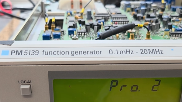
The Philips PM5139 is not famous. It won no great victories on the battlefield, nor was instrumental in changing the political landscape. It was just a useful function generator that you might find on a workbench somewhere, doing its job quietly and relatively accurately. [doctormord] has been doing the work to reverse engineer this humble piece of hardware.
The PM5139 is poorly documented; the only existing service manual out there is for the PM5138A, a less-capable sister model. Hence, there was some value in reverse engineering the device to understand it better. Work started with two EPROM dumps capturing what Philips put in the box all the way back in the early 1990s. From there, the code was examined and tinkered with until [doctormord] felt confident to modify it and improve upon what was already there. This was achieved with the aid of an 8051 emulator that could run the code to make it obvious what was going on. The result was a custom “V2.0” firmware that adds six arbitrary waveforms to the function generator and the ability to play simple music, amongst other tweaks.
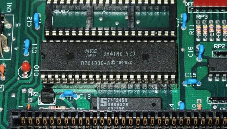
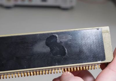
The NEC V20 is an Intel 8088-compatible processor that features the same use of microcode, though with its own characteristics. This makes it important to use this same microcode if your goal is to create a cycle-accurate emulator of this processor, as [GloriousCow]’s goal is. Cue decoding the microcode ROM in a die shot of this CPU, in order to create a usable ROM image.
As with any fabricated ROM you can technically do it by hand, the ROM section in the die shot contained 29,928 bits which even at a pretty zippy pace would take up a considerable amount of time to parse. Here you can divide-and-conquer by handing parts of the ROM off to good friends, or you can use automation and some machine vision and theoretically get an answer as soon as you have finished writing and testing the tool.
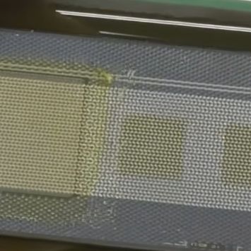
Close-up of some of the microcode bits.
Although [Travis Goodspeed]’s MaskRomTool exists exactly to automate bit detection, it was found that there wasn’t enough contrast in the die shot for it to work reliably. What it did provide were the locations of the bits and from it 42×42 pixel PNG files of each bit.
Next a convolutional neural network (CNN) was trained to determine the difference between a 0 and 1 bit. This still took the manual classifying of 1,000 images, but seemed to work fairly well. Although some bits were marked as ambiguous, it was easy enough to use Mark 1 eyeballs to run a classification on these handful of images than to tweak the CNN model.
With this microcode in hand it was then possible to match it against the V20’s internal architecture to fully determine what each part does. Although not quite finished yet, there’s a GitHub repository containing the progress so far.
The V20’s microcode has been the focal point of much legal fighting back when NEC and Intel were still duking it out in how far one could make a CPU compatible with that of a competitor.
If you are a regular reader, then the odds are you have taken apart an electronic gadget, either for a fix, or simply because your curiosity got the better of you. Once inside, it’s all but impossible to help yourself from doing at least a little reverse engineering. That’s what happened when [PRBS23] took a look inside a MasterBuilt Gravity 800 Grill for a simple wire fix. But one thing led to the next, and now open source firmware for the grill is freely available!
The thermistor along with the physical inputs are connected to a 16 pin chip, interfacing with the MCU over a 9600 baud UART connection. [PRBS23] cannot determine an ADC chip meeting these specifications, so the most likely answer is a cheap MCU programmed to act as a simple analog fronted.
The neatly labeled programming header is used to quite easily dump the firmware with the espflash utility. Analyzing this dump reveals a rather strange ADC correction function used by the original firmware. The necessity and overall utility of this function remains unclear, does corrects a maximum of around 40 degrees Fahrenheit.
Most of the other features ended up being at least somewhat easier. The CS1621 segmented display driver is reasonably well documented with datasheets making its implementation far easier. Likewise, the other odds and ends were implemented in a far more normal manner compared to the thermistors.
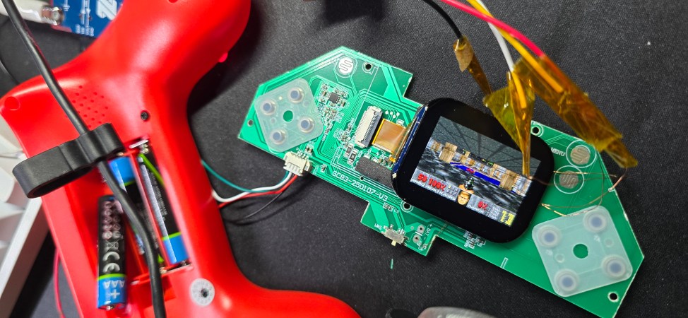
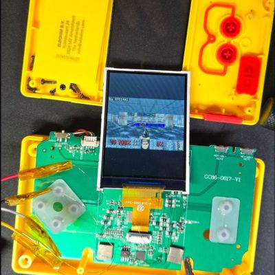
Taking a break from putting DOOM on devices that absolutely were never conceived for use as gaming devices, [Aaron Christophel] recently got enticed by some cheapo handheld gaming systems at his local Action budget store. One is a controller-shaped ‘mini game console’ with 104 games from the 1980s and 1990s, while the other is simply a Pac-Man handheld in a more typical rectangular form factor. Although this brings to mind basic blob chips and limited hacking potential, as it turns out they’re actually quite nice inside.
As also covered in the demonstration video, rather than said nasty blob chip, both handhelds turned out to use the same unmarked MCU in QFN48 packaging. Some prodding and poking confirmed that it’s a typical ARM core, specifically a Cortex-M33 compatible STAR-MC1 ARMv8-M from an unknown manufacturer. Without a datasheet to go by, its limitations had to be discovered experimentally.
Of those, the biggest were a clock speed of 62 MHz – instead of the typical 194 MHz – as well as a lack of sound. This latter issue might be fixable with a better understanding of what appears to be a quirky DMA-fed DAC. Beyond this you’re also dealing with limited memory and of course just 4 MB of flash, though the chip for this might be upgradable if the MCU can map more. You do get a 320×240 display and a lot of buttons, which is admittedly nice.
As for the price difference of around $8/€7 for the Pac-Man version, this appears to be due to it running an officially licensed Bandai Namco arcade emulator as firmware, while the 104-in-one unit runs FlyThings/ZKSWE with a NES emulator.
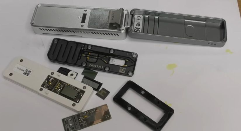
Detail of the nanopore chip. (Credit: mikeselectricstuff, YouTube)
For most people the term ‘DNA sequencing’ probably brings to mind large, expensive laboratory equipment in sterile rooms, but over the past decades technological progress really has had its way with it, to the point where it’s now just another small portable device. Something like the Oxford Nanopore MinION unit that [Mike] recently took to bits to ogle at the intricate insides.
This device was trialed in 2014 in a limited release before its commercial release in 2015, with this paper by [Miten Jain] et al. in Genome Biology detailing the workings of this nanopore sequencer. At a mere $2,000 it’s rather remarkable how affordable it is, though this comes with the caveat of the consumables, which are also shown in the video. These come in at a cool £690 per unit, can sequence either RNA or DNA and can be used at most a few times before they need to be replaced.
The main unit is fairly simple, featuring a Xilinx Spartan 6 FPGA and a rather nice slim fan-based cooling solution. For the nanopore unit you get the typical microfluidics system, to guide the deposited fluid containing the genetic material to sequence over the nanopore system. In here we see the actual magic as well, in the form of the high-density pitch ICs on both sides of the PCB inside the consumable sequencer unit.
Although this particular unit got discontinued already, the consumables are still available for it if you are feeling the sequencing itch. Of course, we’re likely to see the costs for DNA and RNA sequencing to keep plummeting, as what were once complex chips get overtaken once again by the progress of technology.
It’s rather awkward when you buy a piece of hardware like a sketchy router to make a video about its hidden admin password backdoor – known as CVE-2026-11405 – only to discover that you bought the wrong Tenda router, namely the AC10V6 model. After making this mistake, [Low Level] did the only reasonable thing one ought to do in this case, and try to find an exploit in this ‘wrong’ router as well.
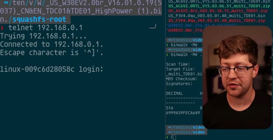
The obvious start here is to do the same as with the other exploit, in that you download a firmware image from the manufacturer’s website, then pluck it apart using binwalkto do an initial check for juicy files. After that tools like Ghidra can be used to do a more in-depth analysis of any binary files, with a special focus on things like user-facing elements like login screen, as input validation will likely forever remain the number one type of exploited CVE.
One major change that Tenda made here was to encrypt the firmware image, which seemed suspicious. With that easy path blocked, the research of others on different Tenda routers was looked at, including the AC20 with the fascinating Telnet exploit in the form of CVE-2025-9090 where merely poking a file on the device turned on the Telnet service. This left the minor issue of finding a password to log into said Telnet session.
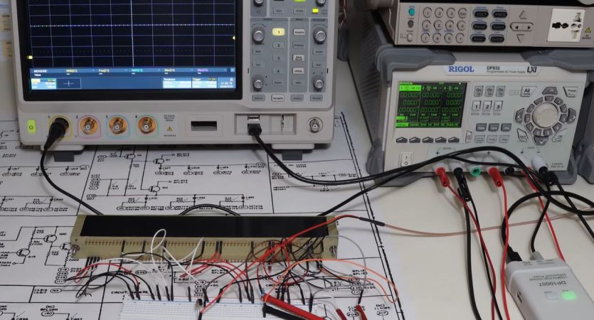
After getting his hands on a rope driver module from the Apollo project era that had a big ‘Scrapped Module’ stamped on it, [Mike Stewart] was naturally left curious as to what exactly had failed in this module. Originally destined for the Apollo Guidance Computer, these Raytheon-manufactured modules were the pinnacle of space-grade high-tech of the 1960s, with requisite acceptance testing so as to not endanger a very expensive space mission.
The cool part here is that the acceptance documents for the module in question (B16-B17) have been scanned in and can be found on the Internet Archive. With the part itself being potted and very much inaccessible, this document helpfully lays out the expected measurements on the module’s pins, as well as schematics and mechanical drawings. Unfortunately the reasons for the rejection were not recorded, so replicating the failing test results is required to understand the reason.
NASA Rope Driver Module with suspicious exploration marks. (Credit: Mike Stewart, YouTube)
A slight complication here is that the testing procedure doesn’t just involve hooking up a multimeter for some voltage and capacitance measurements. There are also temperature and voltage extremes, and vibration tolerance involved, which would be somewhat complex to test, but most of all risk damaging a historical artefact. Thus a somewhat conservative testing procedure was chosen, even if this may not reveal the actual fault.
As noted in the video, sometimes modules were also rejected because someone simply dropped it on the floor along the way. However, generally if a module was found to be faulty they would open it to diagnose said fault, with a closer look at this module indeed revealing suspicious marks in the potting compound where it was apparently opened and conceivably repaired. This also might explain why they also put the ‘For engineering use only’ on it.
With multiple of such locations visible in the potting compound, these locations were mapped to the schematics for the module, to get some idea of what may have been accessed. After this, basic testing was performed on the module, as per the acceptance testing document.
Along the way an error was detected in said document, in the form of the wrong pin number. In table 4-2 the input pin 269 was mistakenly listed as having output pin number 169 when it should have been pin 168. Pin 169 is chassis ground, so this was presumably fixed in a later version of the document.
After all the testing with just stationary, room-temperature conditions, everything appeared to check out. This means that likely this was indeed a repaired module that got subsequently used for engineering purposes rather than installed in flight-ready hardware. The only issue found was that channels were out of calibration, but whether this was an original flaw or due to the module being half a century old is hard to tell in the absence of repair logs.
Overall it’s an exciting opportunity to document another part of history, since so many of the details pertaining to these original modules and related technologies got lost or muddled over the decades.