Image

One Commodore, Five Displays

If you had one monitor back in the 8-bit era, instead of having to wait to use the family TV, you were already amongst the blessed. If you had five, maybe you worked at a computer store– but if you did, you could have done what [The 8-Bit Guy] demonstrates in a recent YouTube video and plug all five (5) monitors into a Commodore 128.

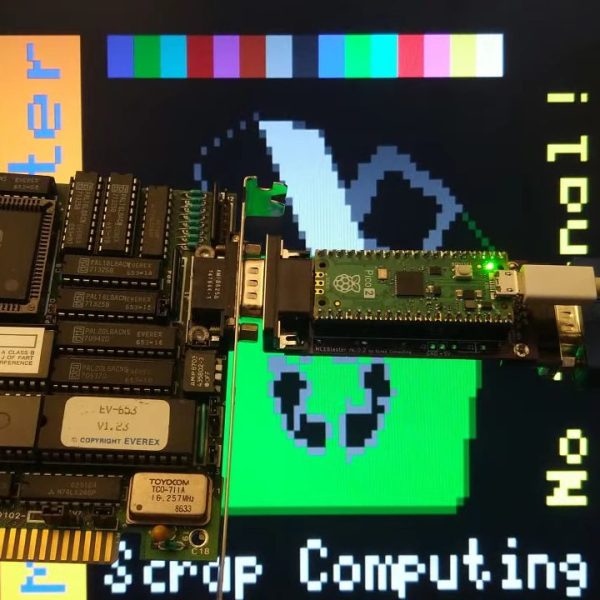
The computer isn’t modified in any way– well, except for the now standard use of an SD card disk emulator– so what gives? Well, you probably guessed he’s splitting up the colour signal into multiple monochrome images, but since the C128 actually has an RGBI, that I– intensity– actually gives another signal that can be broken out. That makes for four screens being driven from that port via composite, all sharing the same sync. The hardware for that was actually designed for [The 8-Bit Guy] by [Joe Burks] who open sourced the design on GitHub. He’s also selling them on Lectronz.

The fifth screen, of course, is driven by the VIC-II chip that Commodore provided for composite output to begin with. The interesting part is as much the software as the hardware, and while [The 8-Bit Guy] explains some of the thinking behind what he’s doing, he doesn’t link to any BASIC. If you know your way around a Commodore, you should be able to encode the multi-colour images required to do the splits.

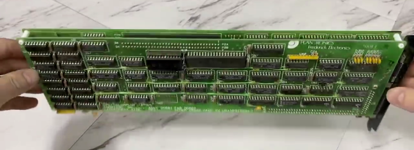
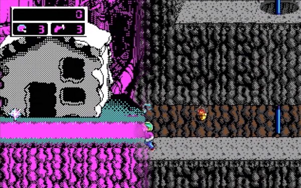
For the people who prefer “real computers” — that is IBM compatible PCs– [The 8-Bit Guy] goes a bit outside of his 8-bit comfort zone to demonstrate that this same trick works quite well with the 16-color modes of EGA. With sixteen colours split between the two monitors, you of course get two colours each– combine the dithering with the blur of an old CRT, and it looks better than it has any right to. Just note that you need to have the right EGA card, as some blocked the 16-colour modes when set to output IRGB/CGA– he used a Trident card to good effect. The software here, though, was just Deluxe Paint, which can’t stop winning, even after four decades. 

The hack seems simple enough, and perhaps everyone knew about it back in the day, but this is the first time seeing it for this author. So we’ll leave it to the comments: have you ever seen a 5-display Commodore, or 4-screen EGA output done like this?

Of course CGA had some competition back in the 80s, and it would be fun to see how many retro standards this trick would work on; at the end of the video [The 8-Bit Guy] discusses splitting VGA signals, but that’s only three screens and way too new for him. If one of you takes up his challenge, please let us know. 

Image

MCE Blaster Translates TTL For Modern(ish) Monitors

VGA isn’t much used anymore, but it’s not hard to get a hold of monitors with that input. How about the older standards like EGA, CGA, or MDA? Well, it’s good luck on eBay or at the recycling yard to get a period-appropriate monitor, but the bulky, fragile CRTs seem to have been less likely to survive than computers that drove them. That’s what [Scrap Computer]’s MCE Blaster is for: it sits betwixt the retrocomputer’s TTL output and the VGA input of a (more) modern monitor, be it CRT or LCD.

Continue reading “MCE Blaster Translates TTL For Modern(ish) Monitors”

Image

A Digital Camera For The 1984 Market

Digital cameras are a ubiquitous consumer and professional product here in 2023, and because of the wide availability of parts it’s relatively straightforward to construct one for yourself. Four decades ago though, film was king, but that hasn’t stopped [Georg Lukas] from building a digital camera for the 1984 market. The hardware is definitely from recent years, the extremely affordable ESP32-cam board that many of us will have worked with already. Meanwhile the 1984 part lies in the recording format, it makes EGA 16-colour low-res pictures and stores them in the archaic TGA file format.

A low-res camera is fun, but there are two other angles on this which are definitely worth some time. The first is that his description and code are worth a read for anyone with an interest in programming an ESP32 camera, while the second invites us to consider whether such a camera could have been made using parts available in 1984. We remember camera peripherals for 8-bit microcomputers which were a C-mount lens positioned over a decapped RAM chip, and thus we can’t help wondering whether an RGB split to three of those sensors could have been constructed. Whether a 6502 or a Z80 with 64k of memory could have processed the three images into one is another matter, but at least if any of you want to try there’s a handy 1984 computer still popping up on eBay.

Image

CGA Competitors From The 1980s

[David Murray], aka The 8-Bit Guy, did an interesting video (embedded below the break) on the time line of PC graphics cards from CGA through to EGA. Not only does he explain the different offerings of the day, but also proceeds to demonstrate most of them.

ImageIt’s interesting to learn about some of the video modes that went basically unused in these cards. Even if board designers include high resolution modes and better color palettes, if software programmers don’t use them they are forgotten.

We were particularly impressed by a couple of examples he had that were full-sized, double-stacked ISA cards — those were beasts. Both CGA and EGA sort of withered when the 1990s arrived.

According to [David]’s research, CGA monitors continued to be used for some time even after EGA was introduced — primarily because of cost. It might cost you $400 to get an ATI EGA Wonder card, and that or more for an EGA monitor. Many folks just upgraded the card first, and took advantage of the fact that the EGA Wonder could drive CGA monitors.

If you are interested in the history and technology of these old cards, check out our coverage from 2016 where [David] does a deep dive into CGA cards and discusses, among other things, the CGA composite video mode.

Continue reading “CGA Competitors From The 1980s”

Image

A Comparison Of Early Graphics Cards

We have to admit, we expected to be bored through [The 8-Bit Guy]’s presentation, only to stay riveted through his comparison of early graphic card technology.

Some presentations get a bit technical, which isn’t bad, but what is so interesting about this one is the clear explanation of what the market was like, and what it was like for the user during this time. For example, one bit we found really interesting was the mention of later games not supporting some of the neat color hacks for CGA because they couldn’t emulate it fully on the VGA cards they were developing on. Likewise, It was interesting to see why a standard like RGBI even existed in the first place with his comparison of text in composite, and much clearer text in RGBI.

We learned a lot, and some mysteries about the bizarre color choices in old games make a lot more sense now. Video after the break.

Continue reading “A Comparison Of Early Graphics Cards”

Adding A SCART Input To A Console VGA Converter

Image

If you’re working with a CGA, EGA, or RGB gaming system this inexpensive board does a great job of converting the signal to VGA so that you can play using a modern display. But what if you have a SCART connector as an output? That’s the situation in which [EverestX] found himself so he hacked in SCART support.

The first step is to source a female SCART connector. He grabbed a coupler off of eBay and cracked it open, yielding two connectors. Now comes the wiring and you may have already noticed that there’s a lot more going on here than the color channels, sync signal, and ground. Technically that’s all you really need to make this happen, but the results will not be good. First off, the sync signal for SCART tends to be rather awful. That’s where the blue breakout board comes into play. [EverestX] used an LM1881 to grab the composite sync (yes, composite sync, not component sync) signal as a feed for the VGA converter. He also added in an audio jack for the sound that is coming through the connector.