Image

Learning About Ground Loop Isolators Thanks To A Scam Product

When [Denki Otaku] bought a ¥1,200 (roughly €6.5) XLR ground loop isolator off Japanese Amazon, he initially didn’t suspect that anything was off. Since they’re fairly simple devices, with basically a 1:1 transformer per channel in some kind of enclosure, the price wasn’t unreasonable.

Image

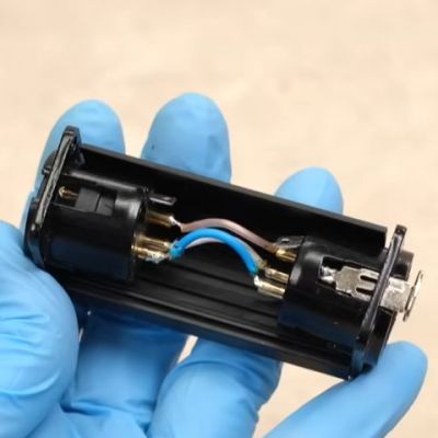
That’s before a teardown showed that this ‘ground loop isolator’ actually contains direct wiring between the XLR sockets, but that doesn’t mean that you cannot still make an educational video about the real devices.

First the basic theory is explained, before the fake ground loop isolator is subjected to an analysis, showing why you’d want to use the real deal. Of course, detecting a fake one is pretty easy, as a simple continuity test with a multimeter  or similar will show that DC passes right through the fake isolator.

Next a real ground loop isolator was designed with a custom PCB and a high-pass filter added to the feature list. Here rather than a very basic filter with cheapo parts there was definitely some gold-plating going on, but it does show what you can do in addition to just adding a few simple transformers for ground isolation purposes.

Image
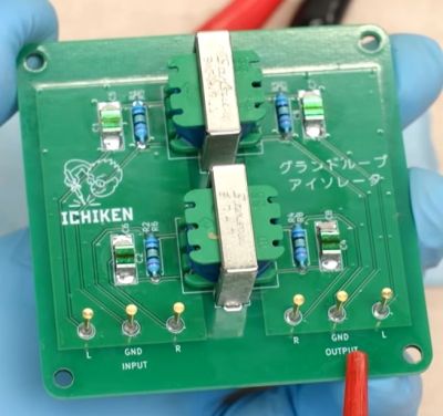
The finished ground loop isolator device is pretty large, and would definitely require a larger enclosure than the homeopathic device, but it makes for an easy test bed with convenient access during the subsequent analysis.

Here each of the two channels has its own transformer and filter, with an initial test just by ear making the injected 2 kHz noise signal appear to go completely away.

Next, an oscilloscope is used to visualize the functionality, with the non-isolated 440 Hz test signal first shown with and without the injected noise, showing the clear impact of the noise and subsequently the isolator.

Of course, high-frequency noises will still pass through the transformer via parasitic capacitance leakage between the windings, so it’s not a silver bullet. Here the analysis at the end of the video shows the noise-rejection characteristics of these isolators, and why adding a high-pass filter makes a lot of sense. Finally, the scam device’s XLR connectors were reused in an enclosure for this custom board, giving it some purpose after all.

Continue reading “Learning About Ground Loop Isolators Thanks To A Scam Product”

Image

They Don’t Make $37 Waveform Generators Like They Used To

[CreativeLab] bought a cheap arbitrary waveform generator and noted that it only had a two-pin power cord. That has its ups and downs. We feel certain the intent was to isolate the internal switching power supply to prevent ground loops through the scope probes or the USB connector. However, it is nice to have all your equipment referencing the same ground. [CreativeLab] agrees, so he decided to do something about it.

Opening the box revealed that there was hardly anything inside. The main board was behind the front panel. There was also the power supply and a USB board. Plus lots of empty space. Some argue the case is made too large to be deceptive, but we prefer to think it was to give you a generous front panel to use. Maybe.

It was a simple matter to ground everything to a new three-pin connector, but that left the problem of the USB port. Luckily, since it was already out on its own board, it was easy to wire in an isolator.

Honestly? We’d have hesitated to do this unless we had made absolutely sure it didn’t pose some safety hazard to “jump over” the switching power supply. They are often isolated for some reason. However, the likelihood is that it is just fine. What do you think? Let us know in the comments.

A similar unit had a reverse engineering project featured on Hackaday many years ago. While these used to be exotic gear, if you don’t mind some limitations, it is very easy to roll your own these days.

Continue reading “They Don’t Make $37 Waveform Generators Like They Used To”

How To Stay Grounded When You Have Zero Potential

Ground is an interesting topic when it comes to engineering. Either it’s the reference level for a digital circuit (not necessarily at zero volts, either), or it’s the return path for current, or it’s the metal chassis, which shouldn’t be the return path for current or else something’s terribly broken. Erika Earl’s talk at this year’s Hackaday Superconference is all about ground.

The first type of ground to talk about is the ground in your outlets and walls. The AC safety ground is the third pin on your plug that should be attached to the chassis of your washer/dryer on one end, and somehow connected to the neutral wire somewhere near your breaker box. The theory of this being if a conductor touches the chassis of a lamp or appliance, all the current will go along that ground bus saving you from electrocution. It should also trip the circuit breaker.

But really we’re rarely dealing with mains power around here. When it comes to electronic design, we’re mostly dealing with analog grounds and digital grounds in circuits. Sometimes these are the same, sometimes they’re not, but they’re both usually referenced to 0 Volts, Add in some considerations for EMC, and ground loops, and you have an astonishing amount of knowledge wrapped up in having zero potential.

If you want to know about what ground actually is, this isn’t a talk to miss. Erika has tons of experience chasing down grounds as an audio engineer, and her career highlights including the director of hardware engineering at Slate Digital and the Senior Technical Engineer at LA’s legendary Village Recording Studios. There’s a lot of experience here, and if you want to where to find your ground, Erika is the person to ask.