Image

Floating-Point Addition And Subtraction On Intel’s 8087

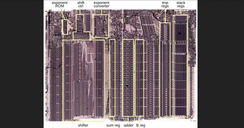
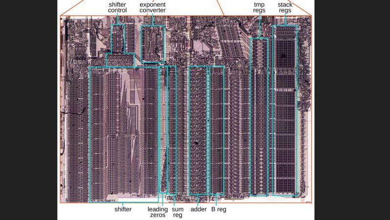
Although you can do basic floating point format operations like addition and subtraction just fine on any CPU, having specialized hardware for it can provide a significant speed boost. Here Intel’s 8087 was the first mainstream floating-point coprocessor to provide this option to a wide audience, with [Ken Shirriff] recently reverse-engineering using an 8087 die how these basic operations were implemented.

The real-world speed-up of even simple operations like adding two floating point numbers compared to the 8086 CPU was on the order of a hundred times, which is very relevant the moment you start doing interesting things with spreadsheets, not to mention rendering 3D scenes in CAD software or even games.

As always, the devil is in the details, with sneaky infinities and edge cases also providing the biggest potential for speed-ups in dedicated silicon, along with the large circuitry spent on the shifter. With floating point values being very much about aligning values with shifting by a number of bits, this circuitry along with the detecting of over- and underflows is the key element why the 8087 and its successors were so crucial in making floating-point operations at all feasible in PC applications.

How this shifting works in theory is detailed in the article by [Ken], along with how the 8087 implements this in its circuits. Naturally, a large part of this is implemented in microcode, the listing for which is also provided. From this it’s quite clear how what seems like a simple set of operations is actually quite complex, making even the now much maligned x87 ISA an improvement over doing it all in integer-based software.
Image

Own The OSD Chip In Your Cheap Composite Monitor

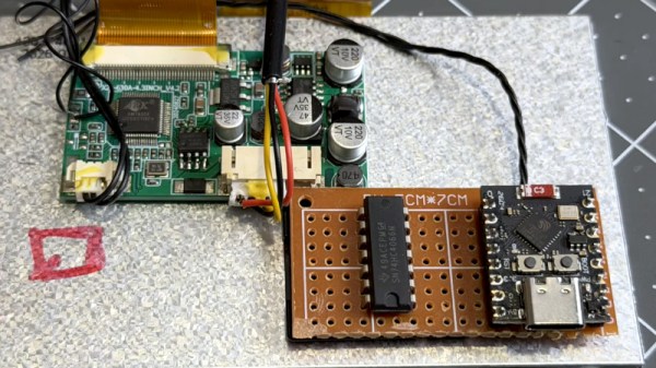
[Ogrinz Labs] has built a Robbie the Robot suit, which is super-cool, but has a huge flaw. When inside the suit, he’s too tall to do what the original Robbie actor did, which was to look through the “mouth” grille. He solved this with an inexpensive automotive reversing camera, but then realised its monitor had a built-in on-screen-display chip. After a lot of work, he’s published a GitHub repository that allows access to this thing for custom on-screen graphics.

The chip in question is an AMT630A, which contains video switching hardware, a graphics system for the on-screen-display, and an 8052 microcontroller core. He didn’t manage to get into the 8052’s brain, but the video below details the long path towards controlling it through an I2C port with an ESP32. The software is available as an Arduino library. His intention is to use it as a display for navigational sensor data to aid in maneuvering Robbie.

Given the status of Robbie as a sci-fi movie icon, it should come as no surprise that we’ve featured this suit before,

Continue reading “Own The OSD Chip In Your Cheap Composite Monitor” →

Image

Teardown Of A USB-C Cable With Integrated LCD

The past years we have been seeing screens pop up in many new places, but seeing them in USB-C cables is still a bit of a novel thing. Out of sheer curiosity [Aaron Christophel] recently took apart one of these, to see what’s inside and what else you can do with them beyond fondling its single touch control and watch reported voltages and current.

Image

Naturally, these devices aren’t exactly meant to be serviced by anyone, so the biggest challenge is to get into them without too much violence. Risking a blood sacrifice to the Hardware Gods, [Aaron] first attacks the display cover of this €15, 240 Watt-rated UGreen cable with sharp utensils before just taking apart the aluminium case, which ultimately gets him inside.

After this it’s clear that attacking the display cover was the right way, just requiring knowing where to apply pressure in order to invert the assembly process. Following that it’s less clear how it was assembled, though it may have involved liberal amounts of glue after sliding in the components. Rather than bothering with applying heat, instead some side-cutters quickly take care of that pesky aluminium shell.

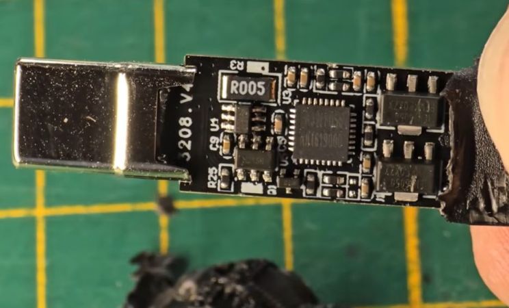
The tiny IPS LC display is attached via a flat flex cable to the PCB with a connector, with the PCB featuring multiple voltage regulators, a MOSFET for the backlight and other parts in addition to the EN32LF056 marked MCU. After some prodding on the exposed SWD interface, it was confirmed to be a Cortex-M0+-based MCU with 64 kB of Flash and 4 kB of SRAM, which made it easy enough to use the little display to display some video frames of everyone’s favorite artist.

Since this MCU is only wired up to measure currents and voltages it cannot use the USB interface, but with some knowledge of how to non-destructively disassemble one of these connectors at least to the point of accessing the SWD pads underneath the display it could be a fun party trick to reflash the firmware with something custom.

Continue reading “Teardown Of A USB-C Cable With Integrated LCD” →

Image

Going On A Tangent With The Intel 8087’s Hybrid CORDIC Algorithm

Continuing their reverse-engineering of Intel’s 8087 FPU, [Ken Shirriff] and friends took a look at one of the trigonometric functions, specifically FPTAN.  The most exciting part with such reverse-engineering is probably figuring out which algorithm was used in the implementation, while trying to determine the reasoning behind the final hardware design.

If you’re running a simple MCU or MPU like the 6502 or Z80 without hardware functions you’d likely use an algorithm such as CORDIC or similar, as this requires only basic hardware features like addition, subtraction, bitshift, and look-up tables. One can also use polynomial approximation if there’s hardware support for a potential speed-up, or as is the case in the 8087, create a hybrid approach that targets speed and accuracy.

In the article the exact implementation to get to 64 bits of accuracy is detailed, starting with the 16 bits calculated using CORDIC before switching to the Padé approximant technique involving the ratio of two polynomials. Since after calculating the brunt of the final value with CORDIC the remainder is a fairly small value, this polynomial approximation is not just very accurate but also fast.

This approach allows the FPTAN and similar trigonometric functions in this FPU to hit a very high level of accuracy and not require the look-up table sizes and additional time required to work through the remaining bits with CORDIC. For those who want to see the full algorithm Intel’s engineers used, [Ken] has the full microcode listing with comments in the article as well.

As for the exact speed-up from this approach, [Ken] calculates for one value that FPTAN would spend 33% on CORDIC pseudo-division, 47% on CORDIC pseudo-multiplication and a mere 15% on the polynomial approximation along with about 5% overhead.

With the Pentium series of CPUs Intel moved completely away from CORDIC, as it’s clear that as accurate as it may be, it’s hard to scale to a significant number of bits without incurring significant time penalties. With the introduction of SIMD instructions the x87 ISA has further seen its functionality reduced, but this analysis shows once again why the 8087 made such an impact when it was released.

Image

Reconstructing Device Firmware From SPI Reads

If you wanted to extract the firmware from a mystery device, you might pull the flash chip out of it and toss it into a reader. But if you only had one chance to get it right and couldn’t risk damaging the device in the process, physically removing the chip may seem much less attractive. Reading the chip in-circuit failed — because of course it did — so what does that leave?

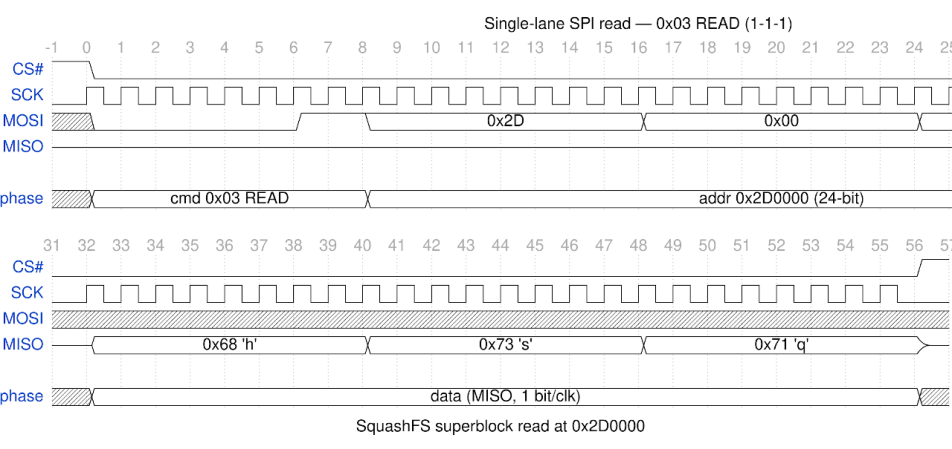
Well, if you follow the example of [Matthew “wrongbaud” Alt], the next tool you reach for might be a logic analyzer. In a recent write-up, [wrongbaud] explains the process of identifying, capturing, and ultimately decoding the SPI read operations used to load the firmware from a common W25Q-series flash chip at boot time. He notes it’s not a perfect solution, as in the end you’ll only be able to sniff out what the CPU actually reads, not necessarily the entire contents of the chip, but it’s a big step in the right direction if you’re reverse engineering something in the dark.

Continue reading “Reconstructing Device Firmware From SPI Reads” →

Image

Reverse Engineering A Sony Car Stereo LCD

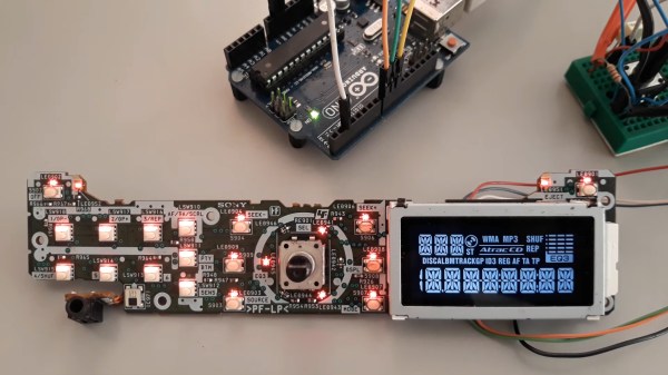
For his own reasons, [Jose Luis Monteiro] (aka [emsyscode]) decided he needed to drive the LCD on a Sony CDX-A250 car stereo’s front panel using an Arduino. There’s probably a sweet project in the works, or perhaps he just wanted to see if it could be done. Either way, more power to [Jose], because he totally pulled it off and put the results up on GitHub for all to enjoy. There’s also a project video showing how he did the reverse-engineering, which you can see below.

The driver for this diminutive LCD is a chip obviously labeled LC75826W, and that’s what the Arduino ends up talking to. Thankfully, there was a datasheet available for that part, which gave [Jose] a great starting point for figuring out how to use it. While [Jose] is working with the LC75826W driver, he’s quite explicit in his GitHub repo that this repository is not a driver library for that chip. The code only targets the specific LCD on the CDX-A250 head unit. Still, if you’ve got a different oddball LCD that uses this driver, [Jose]’s code is a great place to start, and since it’s under an MIT license, you can fork to your heart’s content.

Kudos to Sony for not obfuscating the part or using a chip-on-board black blob — you can reverse-engineer an LCD driven by one of those, but it’s a lot more work. If you’re wondering how and why those black blobs come to be, we’ve got you covered.

Continue reading “Reverse Engineering A Sony Car Stereo LCD” →

Image

Rusting An E-scooter (In A Good Way)

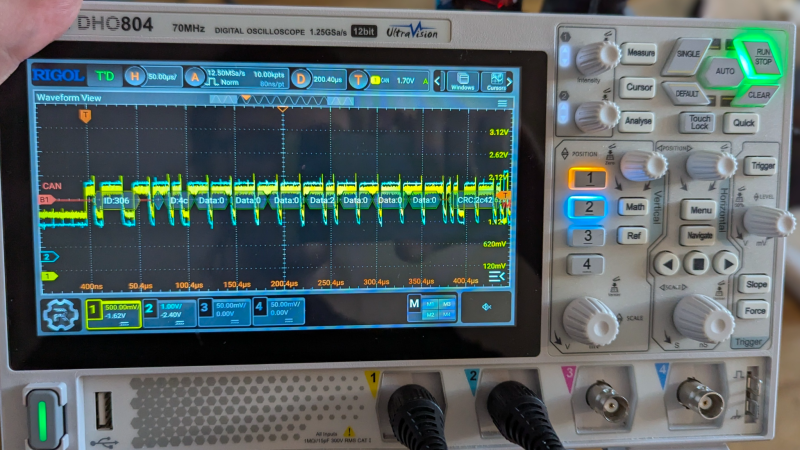
It is a classic Hackaday situation. You have an Egret GT E-scooter. It has a screen that shows the usual dash stats, but that led to an annoyance. You could accidentally enter firmware update mode and, from there, enter operational mode without the security PIN. [Ben] couldn’t let that stand, so he reverse-engineered the protocol and rewrote the firmware in Rust. As he put it, “… because I have to break… everything I own…” We get it.

The mobile app was useful for some basic info, since sniffing Bluetooth is fairly easy and analyzing mobile code is, more or less, straightforward. Analysis revealed some data that doesn’t show on the display and that several things are sent back to home base tagged with the scooter’s unique ID — another reason to gut the existing firmware.

Continue reading “Rusting An E-scooter (In A Good Way)” →