Image

Every Type Of Current Sensor Explained

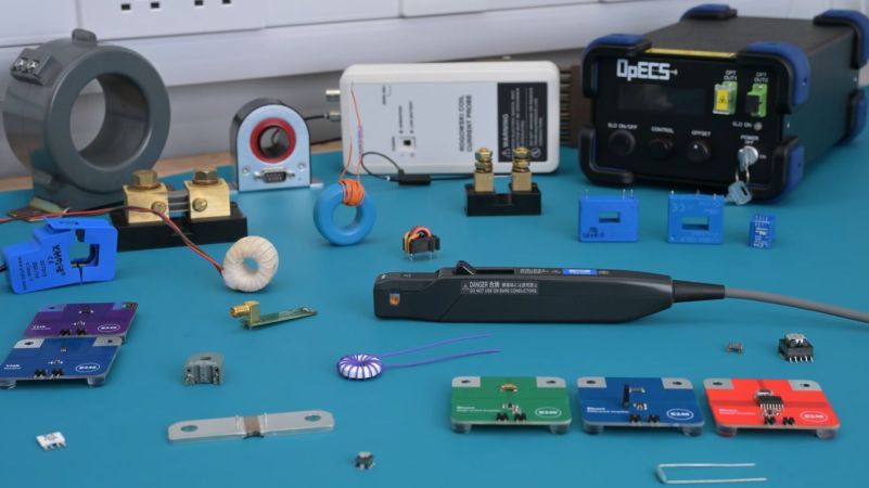
Measuring electric currents is an essential element of many electrical systems, but doing so in a way that is as nonintrusive as possible is not an easy problem to solve. Due to this we got a wide variety of current sensors to choose from for any given application, with [ElectrArc240] running us through these variants in a recent video.

The fairly low-tech, cheap and quite reliable method of using a shunt resistor is first demonstrated. This sees a lot of use in fairly low-voltage and low-current applications, with for example videocards using it to limit the amount of power the GPU can use, a feature that modders will happily bypass. Here simply the voltage drop across a known resistance value is measured, from which the current can be derived.

Of course, you got higher voltage and higher current applications too, as well as direct- and alternating current, with the latter especially allowing for easy current measurements simply from the electromagnetic field, or flux. Anyone who has used a clamp meter can attest to that such contact-free current sensing works, even for DC applications.

Beyond the basic transformer type you got many variants including Hall-Effect, TMR and fluxgate sensors, as well as the fiber-optic current sensor that uses an interferometer to measure the phase-change induced by the magnetic field – the Faraday effect – to the transmitted electromagnetic radiation. These more exotic types will improve resolution, at the cost of a rapidly increasing void in your project budget.

These various sensor types and their construction are demonstrated and discussed in the video, including when you’d want to use a specific type, and what the potential gotchas are with each type. Even if for many applications a simple shunt resistor suffices, it’s a good idea to know these different types, as well as their underlying theory of operation.

Continue reading “Every Type Of Current Sensor Explained” →

Image

2023 Hackaday Prize: A Smart Powermeter That You Actually Want

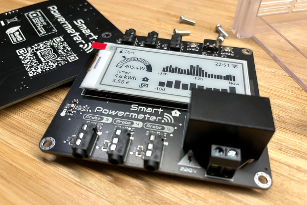
[Jon] wanted to keep track of his home power use, but didn’t want to have to push his data up to some cloud service that’s just going to leave him high and dry in the future. So he went completely DIY.

This simple and sweet build is now in its third revision, and the refinements show. A first prototype was nothing more than an ESP32 with a screen and some current transformer (CT) sensors to read the current flowing in the wires in his breaker box. The next version added a PCB and a color screen, and the most recent version swapped up to eInk and a nice local power supply, all sized to fit a nice clear power box.

What’s really cute about this design is the use of standard phono headphone jacks to plug the CT sensors into, and the overall sweet combination of a local display and interactivity with [Jon]’s ESPHome-based home automation setup. This design isn’t super complicated, but it doesn’t need to be. It has one job, and it does it nicely. What more do you want?

If you’re interested in getting into ESPHome and/or home automation, check out this great ESPHome resource. It’s probably a lot easier than you think, and you can build your system out one module at a time. If you’re like us, once you get started, you’ll find it hard to stop until everything falls under your watchful eyes, if not your control.

Image

Air Extractor Automatically Gives AC A Boost

Portable air conditioning units are a great way to cool off a space during the hot summer months, but they require some place to blow the heat they’ve removed from your room. [VincentMakes] got a portable AC unit for his home, but he found that the place he wanted to put it was too far from the only window he could use to dump the hot air. Having too long of a duct on the hot air exhaust increases the back pressure on the fan which could cause it to prematurely fail, so [Vincent] used an extractor fan to automatically give is AC unit’s exhaust a boost on its way to the window.

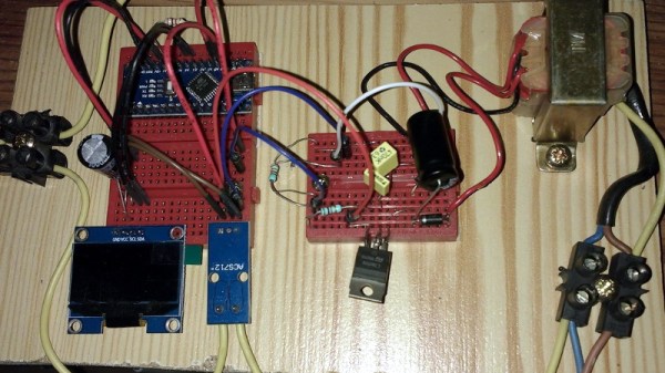
Because his AC can operate at low, medium, and high speeds, he chose an extractor fan that also supported multiple speeds and took care to match the airflow of the AC and extractor fan to avoid putting too much strain on either fan. He designed a system to automatically set the speed of the boosting fan to match that of the AC using a Hall effect current sensor to measure the AC unit’s power draw and an Arduino Nano for control. A custom PCB interfaces the Nano to the Hall Sensor and control relays, and we have to applaud [Vincent] for keeping the +5V DC and 230V AC far, far away from each other. In addition to this fine electronics work, [Vincent] also built an enclosure for the fan controller that allows the fan to be mounted on top at an angle, which helps avoid having hard bends in the exhaust duct.

If this has you thinking about smart air conditioners to keep cool this summer, check out this ESP8266-powered smart AC system, or this Raspberry Pi-based system that controls both AC and blinds!

Image

Laundry Monitor Won’t Generate Static With Roommates

Laundry. It’s one of life’s inescapable cycles, but at least we have machines now. The downside of this innovation is that since we no longer monitor every step — the rock-beating, the river-rinsing, the line-hanging and -retrieving — the pain of laundry has evolved into the monotony of monitoring the robots’ work.

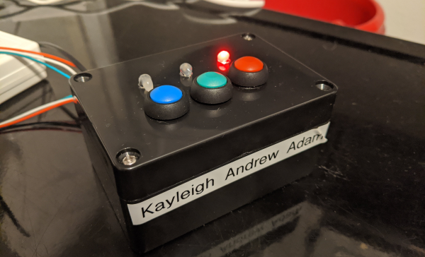
[Adam] shares his wash-bots with roommates, and they aren’t close enough to combine their lights and darks and turn it into a group activity. They needed an easy way to tell when the machines are done running, and whose stuff is even in there in the first place, so [Adam] built a laundry machine monitor that uses current sensing to detect when the machines are done running and sends a text to the appropriate person.

Each machine has a little Hall effect-sensing module that’s carefully zip-tied around its power cable. The signal from these three-wire boards goes high when the machine is running and low when it’s not. At the beginning of the load, the launderer simply presses their assigned button on the control box, and the ESP32 inside takes care of the rest.

Getting a text when your drawers are clean is about as private as it gets. Clean underwear, don’t care? Put it on a scrolling marquee.

Image

Create A Low-Cost, High-Accuracy LCR Meter With An STM32 MCU

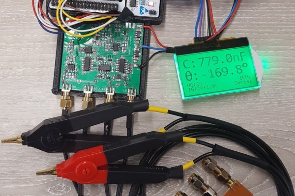
Having a good LCR meter was something which [Adil] had wanted for his personal lab, so as any good university student (and former Hackaday contributor) does, he ended up building his own. Using a Nucleo-F446RE board for the MCU side and a custom PCB for the side that does the actual measuring, he created a meter that reportedly comes pretty close to commercial meters, and for the low price of £55.

Running through some of the theory behind the design as well some design choices, the resulting product is then presented. The choice to not using a standard current shunt, but instead a transimpedance amplifier (TIA) is explained as well. Unfortunately there are no schematics or source code, and the text is somewhat unclear on some points, failing to explain some acronyms that’d make it hard for someone who is not active in this field to understand the full design.

We hope that [Adil] can address those points and provide design files and source code, as it does look like a very interesting project!

Image

Phase Shift Pump Control? There’s An App For That.

The sort of pumps used in the filtration systems of fountains and swimming pools don’t take kindly to running dry. So putting such a pump on a simple timer to run while you’re away comes with a certain level of risk: if the pump runs out of water while you’re gone, you might come home to a melted mess. One possible solution is a float sensor to detect the water level in whatever you’re trying to pump, but that can get complicated when you’re talking about something as large as a pool.

ImageFor his entry into the 2019 Hackaday Prize, [Luc Brun] is working on controller that can detect when the pump is running dry by monitoring the phase shift between voltage and current. With an inductive load like a pump, the current should lag behind the AC voltage a bit under normal operation. But if they become too far out of phase with each other, that’s a sign that the pump is running in a no-load condition because there’s no water to slow it down.

As [Luc] explains in the project write-up, simply monitoring the pump’s peak current could work, but it would be less reliable. The problem is that different motors have different current consumptions, so unless you calibrated the controller to the specific load it’s protecting, you could get false readings. But the relationship between current and voltage should remain fairly consistent between different motors.

The controller is powered by a Arduino Nano and uses a ACS712 current sensor to take phase measurements. Since he had the ability to toggle the pump on and off with a relay attached to the Arduino, [Luc] decided to add in a few other features. The addition of a DS1307 Real Time Clock means the pump can be run on a schedule, and an HC-05 Bluetooth module lets him monitor the whole system from his smartphone with an Android application he developed.

Since the theme of this year’s Hackaday Prize is designing a product rather than a one-off build, judges will be looking for exactly the sort of forward thinking that [Luc] has demonstrated here. As the controller is currently a mass of individual modules held inside a waterproof enclosure, the next steps for this project will likely be the finalization of the hardware design and the production of a custom PCB.

Image

How Current Shunts Work

Current. Too little of it, and you can’t get where you’re going, too much and your hardware’s on fire. In many projects, it’s desirable to know just how much current is being drawn, and even more desirable to limit it to avoid catastrophic destruction. The humble current shunt is an excellent way to do just that.

Image
Ohm’s Law.

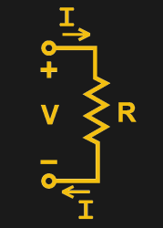
To understand current, it’s important to understand Ohm’s Law, which defines the relationship between current, voltage, and resistance. If we know two out of the three, we can calculate the unknown. This is the underlying principle behind the current shunt. A current flows through a resistor, and the voltage drop across the resistor is measured. If the resistance also is known, the current can be calculated with the equation I=V/R.
Image

This simple fact can be used to great effect. As an example, consider a microcontroller used to control a DC motor with a transistor controlled by a PWM output. A known resistance is placed inline with the motor and, the voltage drop across it measured with the onboard analog-to-digital converter. With a few lines of code, it’s simple for the microcontroller to calculate the current flowing to the motor. Armed with this knowledge, code can be crafted to limit the motor current draw for such purposes as avoiding overheating the motor, or to protect the drive transistors from failure.

In fact, such strategies can be used in a wide variety of applications. In microcontroller projects you can measure as many currents as you have spare ADC channels and time. Whether you’re driving high power LEDs or trying to build protection into a power supply, current shunts are key to doing this.

Continue reading “How Current Shunts Work” →