Contact Sales & After-Sales Service

Contact & Quotation

  • Inquire: Call 0086-755-23203480, or reach out via the form below/your sales contact to discuss our design, manufacturing, and assembly capabilities.
  • Quote: Email your PCB files to [email protected] (Preferred for large files) or submit online. We will contact you promptly. Please ensure your email is correct.
Drag & Drop Files, Choose Files to Upload You can upload up to 3 files.

Notes:
For PCB fabrication, we require PCB design file in Gerber RS-274X format (most preferred), *.PCB/DDB (Protel, inform your program version) format or *.BRD (Eagle) format. For PCB assembly, we require PCB design file in above mentioned format, drilling file and BOM. Click to download BOM template To avoid file missing, please include all files into one folder and compress it into .zip or .rar format.

PCBSync · Assembly engineering & project planning

Wire Harnessing: Plan Routing, Retention and Service Access

Turn a connection diagram into an installation that can be assembled, inspected and serviced. Review branch routes, connector access and movement, then use the length planner to make route and allowance assumptions explicit.

Prototype through production · scope and schedule confirmed after file review

Operator arranging wiring in a row of open electronic enclosures.
At a glance: Wire harnessing includes the physical organization and installation of connections. A harness can have the correct pinout yet still need changes to reach, retention, bend space or service access in the final product.
Prepare a clearer project request

Wire Harnessing tools

Wire Harnessing workbench

PCBSync Engineering Tools · no account required · calculations run in your browser

Mark what you have prepared

Match the scope to the decision

Wire Harnessing: requirements that change the build

Decision / stageWhat to defineEvidence or next action
RoutingDatums, path, clearances and moving zonesRepresentative installation review
RetentionSupports, abrasion protection and strain reliefDefined construction and inspection views
ServiceConnector access, slack and work sequenceRevision-controlled installation instructions
Practical engineering and purchasing guidance

Plan the work before releasing the files

Start from the installed geometry

Locate the actual connector mating faces, mounting points and pass-through features in the product. Define reference datums and show the path between them rather than measuring only a straight line between electrical endpoints.

Review the space needed to insert, latch and remove each connector. Include backshells, strain relief and assembly tools in that access discussion. Where enclosure or board positions can vary, resolve the tolerance stack before deciding the released harness lengths.

Manage movement and mechanical exposure

Identify static routes separately from regions that move during normal operation or servicing. Use cable and connector supplier limits for the relevant construction, direction and duty rather than applying one bend-radius multiplier to every bundle.

Review abrasion, sharp edges, pinch points, heat sources and load transfer into connector contacts. Define support and protection features on the drawing and inspect the proposed installation in representative positions. A protective sleeve does not itself validate movement life or environmental sealing.

Make length allowances visible

Use the planner for one repeated physical cut-piece type. Separate measured route, additional termination allowance and service slack only if those dimensions are not already included in a final cut length.

Record what each datum and allowance means for the selected connector and assembly method. Use the result to prepare a discussion or material scenario, then release production dimensions with tolerances after the installation and build sequence have been reviewed.

Create usable installation and service instructions

Show branch identification, connector orientation, retention locations and the order of operations where access changes during assembly. Provide clear views for areas that will be hidden after the enclosure is closed.

Define the inspection or electrical checks required after installation and after any service operation. Keep the work instruction tied to harness, enclosure and PCB assembly revisions. The NASA reference is an example of a controlled workmanship standard and its scope, not a claim that every commercial installation must meet it.

Keep the review concrete

Include these requirements in your enquiry

01

Connector mating faces and installation datums are shown

02

Routing includes tolerances and physical clearance

03

Static and moving regions are identified

04

Supplier bend and handling limits are reviewed

05

Supports and protection locations are specified

06

Installation sequence and final checks are documented

Mark unresolved items explicitly. Ask the quotation to identify proposed exceptions, required customer approvals and any inspection or special-process charges that remain open.

See the physical construction

Physical harness and integration examples

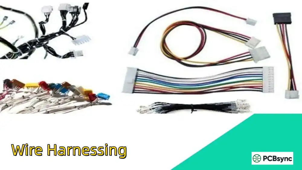
These media-library photographs show wire bundles, connector terminations and enclosure integration. They illustrate construction and access, not a claim of a specific customer project, qualification, certification or measured performance.

Answers before requesting a quote

Wire Harnessing FAQ

Is a universal bend-radius rule suitable for every harness?

No. Use requirements for the actual wire or cable, connector and movement duty, then review the complete installed bundle.

Why is service slack separate from termination allowance?

They address different needs. Termination allowance supports the connection geometry or process; service slack supports installation or maintenance. Do not add either twice.

Can the length tool approve an installed route?

No. It adds your entered dimensions. It cannot inspect CAD, check movement, resolve interference or approve retention and strain relief.

Technical links checked 2 October 2026. Apply the current documentation and project-specific acceptance requirements. Planners do not certify manufacturability or validate uploaded design files.

From planning to a reviewed quotation

Discuss your Wire Harnessing requirements

Send the scope you want reviewed

Add a project brief or reference budget from the tools above. Include your assembly revision, requested quantity, required timing and open engineering questions.

Provide the harness drawing and revision, wire/cable and connector/contact BOM, pin-to-pin connection list, branch dimensions and tolerances, labels and required quantity. Include the installation context, test specification and record requirements. Identify proposed substitutions, supplied materials and unresolved details so the quotation can separate confirmed work from review items.

Email: [email protected]
Phone: +86-755-23203480

Review the message and attachments before sending. An enquiry does not place an order.

Drag & Drop Files, Choose Files to Upload You can upload up to 3 files.