Contact Sales & After-Sales Service

Contact & Quotation

  • Inquire: Call 0086-755-23203480, or reach out via the form below/your sales contact to discuss our design, manufacturing, and assembly capabilities.
  • Quote: Email your PCB files to [email protected] (Preferred for large files) or submit online. We will contact you promptly. Please ensure your email is correct.
Drag & Drop Files, Choose Files to Upload You can upload up to 3 files.

Notes:
For PCB fabrication, we require PCB design file in Gerber RS-274X format (most preferred), *.PCB/DDB (Protel, inform your program version) format or *.BRD (Eagle) format. For PCB assembly, we require PCB design file in above mentioned format, drilling file and BOM. Click to download BOM template To avoid file missing, please include all files into one folder and compress it into .zip or .rar format.

PCB Assembly / Cable Assembly
PCBSync · Assembly engineering & project planning

Cable Assembly Services for Defined Connections and Verified Builds

Request custom cable assembly for your electronic product with the cable construction, terminations and test scope clearly defined. Prepare a project brief, check a simple DC-loop scenario and connect the cable work to PCB assembly or box build.

Prototype through production · scope and schedule confirmed after file review

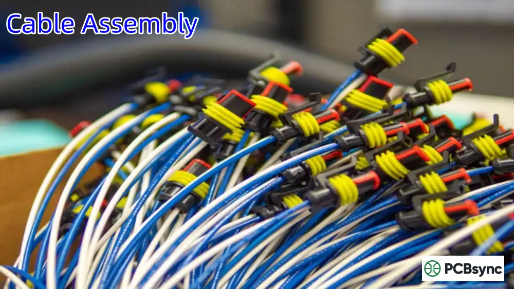
Prepared cable assemblies with wire bundles and connector housings.
At a glance: A cable assembly combines specified cable material with terminations and associated protection or identification. Its electrical performance, dimensions and acceptance criteria come from the controlled design, not the cable name alone.
Prepare a clearer project request

Cable Assembly tools

Cable Assembly workbench

PCBSync Engineering Tools · no account required · calculations run in your browser

Mark what you have prepared

Match the scope to the decision

Cable Assembly: requirements that change the build

Decision / stageWhat to defineEvidence or next action
ConnectionCable, connectors, contacts and pin mappingComplete BOM and mating interface
ConstructionLength datums, clocking and protectionControlled assembly drawing
AcceptanceRequired electrical and mechanical checksLimits, coverage and records
Practical engineering and purchasing guidance

Plan the work before releasing the files

Start with the connection you need to make

Identify the function at each end: power, control, sensor or communication. Provide the mating connector identity, pin assignment and viewing direction, including unused contacts and any shield or drain connections.

Specify complete cable, housing and contact part numbers where selected. If alternatives are requested, define the characteristics that must stay equivalent and require approval before substitution. Connector fit alone does not establish electrical or environmental suitability.

Make the mechanical requirements measurable

State finished length between named datums and the permitted tolerance. Show connector clocking, branch points if present, strain relief and the space available behind each interface for routing and service.

Describe movement, bend constraints, abrasion, fluids and temperature exposure relevant to the application. A sleeve, braid or overmold should solve a defined requirement; its presence does not automatically establish sealing or flex-life performance.

Separate electrical planning from acceptance testing

For a simple two-wire DC load, use the planner with conductor resistance at the relevant temperature and the total resistance of contacts in the complete loop. The output helps document a voltage-drop assumption for review.

It does not select a wire gauge or establish current rating. Define continuity and pin-map checks separately from any specified resistance, insulation, dielectric or signal tests. Give the required limits, method, sampling and record format instead of requesting an undefined full test.

Quote a controlled prototype-to-production route

A useful quotation identifies material supply, termination tooling, fixture or test setup, assembly work and packaging. Separate one-time engineering or tooling charges from recurring unit work and state which requirements are still open.

Review a first article against the drawing and installation before scaling the build. When the cable connects to a PCB assembly or an enclosure in a box-build project, coordinate revisions, mating parts and test ownership so that an individually correct cable also fits the complete product.

Keep the review concrete

Include these requirements in your enquiry

01

Cable and connector/contact part numbers are supplied

02

Pin map and connector viewing direction are explicit

03

Finished length datums and tolerances are defined

04

Environment and routing constraints are described

05

Required test methods and limits are stated

06

Prototype approval and production quantity are planned

Mark unresolved items explicitly. Ask the quotation to identify proposed exceptions, required customer approvals and any inspection or special-process charges that remain open.

See the physical construction

Cable, connector and integration examples

Media-library photographs show physical terminations, wire bundles and system integration. Use your drawing and approved test requirements to define the actual build; these images do not establish a particular product rating or test result.

Browse the supporting pages

Cable Assembly guide library

1 supporting guides

Answers before requesting a quote

Cable Assembly FAQ

What is needed for a cable assembly quote?

Start with the drawing, BOM, pin-to-pin table, quantities and timing. Add length tolerances, environment and test requirements; mark unresolved items for review.

Can the DC tool select a safe wire gauge?

No. It calculates voltage drop from entered resistance and current. Ampacity, temperature rise, protection and product approval require separate engineering evidence.

How does cable assembly differ from wire harness assembly?

Usage overlaps. Describe the actual construction: a terminated cable, a bundle of individual wires, or a branched combination. The drawings and interfaces are more useful than the label alone.

Technical links checked 2 October 2026. Apply the current documentation and project-specific acceptance requirements. Planners do not certify manufacturability or validate uploaded design files.

From planning to a reviewed quotation

Discuss your Cable Assembly requirements

Send the scope you want reviewed

Add a project brief or reference budget from the tools above. Include your assembly revision, requested quantity, required timing and open engineering questions.

Send the controlled assembly drawing, BOM with complete connector/contact and cable part numbers, pin-to-pin table, length datums and tolerances, quantities and required timing. Include electrical and mechanical test requirements, mating interfaces and any marking, packaging or approval requirements. If the design is incomplete, identify the open decisions for review.

Email: [email protected]
Phone: +86-755-23203480

Review the message and attachments before sending. An enquiry does not place an order.

Drag & Drop Files, Choose Files to Upload You can upload up to 3 files.