Inquire: Call 0086-755-23203480, or reach out via the form below/your sales contact to discuss our design, manufacturing, and assembly capabilities.
Quote: Email your PCB files to [email protected] (Preferred for large files) or submit online. We will contact you promptly. Please ensure your email is correct.
Notes: For PCB fabrication, we require PCB design file in Gerber RS-274X format (most preferred), *.PCB/DDB (Protel, inform your program version) format or *.BRD (Eagle) format. For PCB assembly, we require PCB design file in above mentioned format, drilling file and BOM. Click to download BOM template To avoid file missing, please include all files into one folder and compress it into .zip or .rar format.
Flex PCB Assembly: Plan Support, Soldering and Final Form
Prepare flexible circuits for component assembly with a clear plan for support, handling, soldering and the installed shape. Share the BOM, flex construction and mechanical requirements for a reviewed PCBSync quotation.
Prototype through production · scope and schedule confirmed after file review
Branched flexible circuit with populated component islands and interconnecting flex sections.
At a glance: Flex PCB assembly mounts components onto a flexible circuit. Bare-board fabrication, temporary assembly support and final-product reinforcement are separate requirements.
YOUR NEXT ENGINEERING DECISION
Plan an assembled flex, not just a bare circuit
Define component support, carrier strategy, bend restrictions and inspection access. The bare-circuit and assembly scopes must agree before comparing quotations.
Your notes and supported planner selections stay in this browser tab for two hours. They are not submitted here. Review the summary on Contact before sending an enquiry.
Prepare the support, thermal-process and verification decisions that make a flexible assembly different from a bare circuit.
Your next review steps
Match BOM, placement, fabrication and installed-shape drawing revisions. Identify who owns bare-board procurement, components and approved substitutions.
Plan support through printing, placement, soldering, inspection and release. A permanent stiffener does not automatically replace a process carrier.
Define what is inspected before forming and what is verified after forming. Include packaging and handling so accepted joints are not stressed during delivery.
Open detailed calculations and supporting checks
Flex PCB Assembly workbench
PCBSync Engineering Tools · no account required · calculations run in your browser
Mark what you have prepared
Reference SMT processing and stencil budget only. Flex carriers, stiffeners, special handling, forming, reel processing and validation are not priced by this model. Request feasibility and tooling review against the actual construction.
PCBSync engineering tools
PCB assembly & stencil quote planner
Configure the build. See the scope behind the budget.
Choose a supply arrangement. Component procurement and PCB fabrication are reviewed separately from this processing budget.
How this reference budget works
The planner uses the existing PCBSync assembly processing model. Its stencil allowance is USD 35 for a one-side set or USD 60 for a both-side set, multiplied by the number of sets. These are uncalibrated planning allowances, not published selling prices. Frame size, apertures, coating and custom construction require review. Assembly quantity means individual boards, not panels.
The displayed ±12% spread is illustrative, not a validated accuracy claim. Special requirements are listed separately and do not silently enter the total. Turnkey selection does not price your BOM. A final quotation requires engineering review of the actual files and material availability.
Valid planner settings can be retained in this browser tab for up to two hours; assembly and fabrication planners share the board quantity. Contact details and uploaded design files are not stored by this planner.
DESIGN TIP 01
Protect the component island
Review how connector insertion or enclosure movement transfers force into soldered areas.
DESIGN TIP 02
Keep datum references consistent
Relate component placement, tooling and formed geometry to clearly identified references.
DESIGN TIP 03
Check the delivery state
Specify whether circuits arrive flat, formed, panelized or in protective carriers.
Match the scope to the decision
Flex PCB Assembly: requirements that change the build
Decision / stage
What to define
Evidence or next action
Installed use
Static forming or repeated movement
Flat and formed drawings with controlled bend zones
Assembly support
Carrier versus permanent stiffener
Tooling, access and release review
Acceptance
Electrical and mechanical requirements
Agreed inspection, test and handling evidence
Practical engineering and purchasing guidance
Plan the work before releasing the files
Show how the circuit is used after assembly
Include the flexible PCB construction with a flat drawing and the installed shape, marking bend zones, connector orientation and component height limits. Distinguish a circuit formed during installation from one that moves repeatedly during operation.
Keep soldered component areas and mechanical transitions visible in the review. A photograph of a bent sample cannot establish acceptable life or bend geometry for a different stackup. Define the required movement, environment and verification method.
Plan temporary support and permanent reinforcement
A carrier can hold a thin circuit during printing, placement, soldering and inspection. A permanent stiffener supports a selected area in the finished product. One does not automatically replace the other.
Use the flex PCB DFM checklist to review carrier access, fiducials, tooling features, underside components and release method. Include the stiffener outline, material, thickness and adhesive requirements in the controlled construction rather than relying on an informal note.
Review the whole thermal and handling route
The process window depends on the flex materials, adhesives, finish, solder system and fitted components. Review the flex PCB soldering process and request a qualified profile and material-specific moisture handling instead of copying a universal temperature or bake time from another design.
Include cleaning compatibility, coating boundaries, connector protection and permitted rework. Support the assembly during inspection and depaneling so an otherwise acceptable joint is not damaged by uncontrolled bending after soldering.
Define what the quotation and acceptance include
For a turnkey assembly quotation, list the carrier, stencil, component sourcing, forming, testing and packaging tasks that need to be reviewed. The reference calculator prices a limited processing scenario; flex-specific tooling and qualification remain separate.
Ask for evidence appropriate to the product: inspection of critical joints, continuity or functional checks, and mechanical verification where specified. Use the readiness brief to identify unresolved requirements before files are released.
Control the handoff from bare circuit to tested assembly
Before solderingMatched files, material handling and carrier access.
During assemblySupport, process window and inspection access.
After formingElectrical checks, mechanical condition and protective packing.
Start the assembly review with the final product shape rather than only the flat placement drawing. Show the populated islands, flexible interconnects, connector direction and any forming operation after soldering. Identify where an operator may hold the assembly and which areas must not take handling loads. This helps distinguish a manufacturing fixture requirement from a permanent reinforcement requirement in the delivered product.
For a concrete planning example, a populated sensor island connects to a main board through a thin tail. The carrier must support the island during printing and placement while keeping tooling clear of the tail and any underside features. After soldering, the assembly needs a controlled release method. The example does not imply that a particular fixture or process is approved; it identifies the decisions that should appear in the tooling review.
Build the inspection sequence around access and risk. Some features are easier to inspect while the circuit remains flat or supported. Other requirements can only be checked after forming or connector engagement. Specify the electrical and functional checks, the required records and who provides the test instructions. Separate development of a test fixture or program from routine execution of an already approved test.
Finish the plan with packaging and responsibility. State whether the delivered part is flat, formed, panelized or installed in another assembly. Protect exposed contacts and prevent the packaging from loading a bend or component island. For customer-supplied circuits or components, agree incoming checks and how exceptions will be handled. A complete quotation should identify carrier tooling, stencil, component sourcing, test preparation, forming and delivery scope rather than hide them inside an unexplained assembly total.
Review, acceptance and handoff
Check revision consistency before starting the assembly review. The BOM, placement file, fabrication drawing and installed-shape drawing should describe the same build. Identify any components that are not fitted and any options that change the support or test requirements. If the circuit is supplied by the customer, include the accepted bare-board construction and handling information. A correct assembly file cannot resolve an undocumented change in the incoming circuit.
Plan access through the full route. A fixture that supports placement may obstruct a connector, an inspection view or a test point later in the process. Review the sequence for both sides where relevant, including how the assembly is moved and released. Mark temporary attachments and identify which features must remain free of adhesive or other process aids. These details belong in the tooling review rather than being improvised at the final stage.
Keep material handling instructions specific to the supplied construction. Storage, moisture treatment and thermal processing should be based on applicable material and component information. A familiar flex appearance is not enough to select a universal bake or reflow instruction. Ask the review to identify any missing documentation and the conditions requiring customer approval. This is particularly useful when several organizations supply the circuit, components and assembly work.
Define the inspection boundary between fabrication and assembly. Bare-board electrical testing addresses the unpopulated circuit; assembly inspection and functional testing address other risks. Specify what evidence is expected at each stage and how discrepancies will be recorded. If a failure is found after forming, retain the pre-forming observations so the investigation can distinguish an existing defect from damage introduced during handling or installation.
Agree the delivery configuration explicitly. A flat assembly, a formed assembly and an assembly installed into a housing require different handling and verification details. State which organization performs the forming or installation and how the accepted shape is documented. Include packaging requirements that prevent accidental folding or connector damage during transit. Delivery format should be part of the reviewed scope, not a decision left until packing.
For the quotation, separate the work that happens once from work repeated on each unit. Carrier design, test development or process preparation may have a different commercial basis from routine assembly and inspection. Ask which tools remain usable for a repeat order and what changes trigger another review. Carry the resulting assumptions into the purchase package so engineering, purchasing and manufacturing share the same definition of the delivered assembly.
Keep the review concrete
Include these requirements in your enquiry
01
Flat and installed-shape drawings are available
02
Bend zones and movement requirements are marked
03
Stiffener and adhesive construction is defined
04
Carrier and panel support need review
05
Material and component thermal limits are supplied
06
Test, forming and packaging requirements are stated
Mark unresolved items explicitly. Ask the quotation to identify proposed exceptions, required customer approvals and any inspection or special-process charges that remain open.
See the physical construction
Assembly examples from the PCBSync media library
These physical examples highlight component density, access, interconnects and handling details. Identify the features relevant to your design so the engineering review can focus on your actual build requirements.
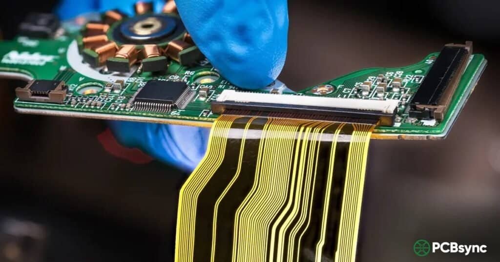
Close view of a populated circuit assembly and flexible interconnect tails.
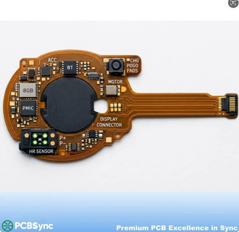
Round flexible-circuit assembly with mounted components and an extended connector tail.
Technical links checked 2 October 2026. Apply the current documentation and project-specific acceptance requirements. Planners do not certify manufacturability or validate uploaded design files.
From planning to a reviewed quotation
Discuss your Flex PCB Assembly requirements
Send the scope you want reviewed
Add a project brief or reference budget from the tools above. Include your assembly revision, requested quantity, required timing and open engineering questions.
For a quotation, prepare the fabrication files, BOM and placement data, plus the drawing and any test or programming instructions relevant to the work. Need an NDA or a specific file-transfer route? Contact us before sharing files.