Contact Sales & After-Sales Service

Contact & Quotation

  • Inquire: Call 0086-755-23203480, or reach out via the form below/your sales contact to discuss our design, manufacturing, and assembly capabilities.
  • Quote: Email your PCB files to [email protected] (Preferred for large files) or submit online. We will contact you promptly. Please ensure your email is correct.
Drag & Drop Files, Choose Files to Upload You can upload up to 3 files.

Notes:
For PCB fabrication, we require PCB design file in Gerber RS-274X format (most preferred), *.PCB/DDB (Protel, inform your program version) format or *.BRD (Eagle) format. For PCB assembly, we require PCB design file in above mentioned format, drilling file and BOM. Click to download BOM template To avoid file missing, please include all files into one folder and compress it into .zip or .rar format.

PCB manufacturing / PCB Antenna
PCBSync · Antenna design & PCB manufacturing

PCB Antenna: Design, Prototyping & Manufacturing

Choose the antenna around the finished product, then control the PCB construction that makes it repeatable.

Stack-up, test scope, price and schedule confirmed after file review.

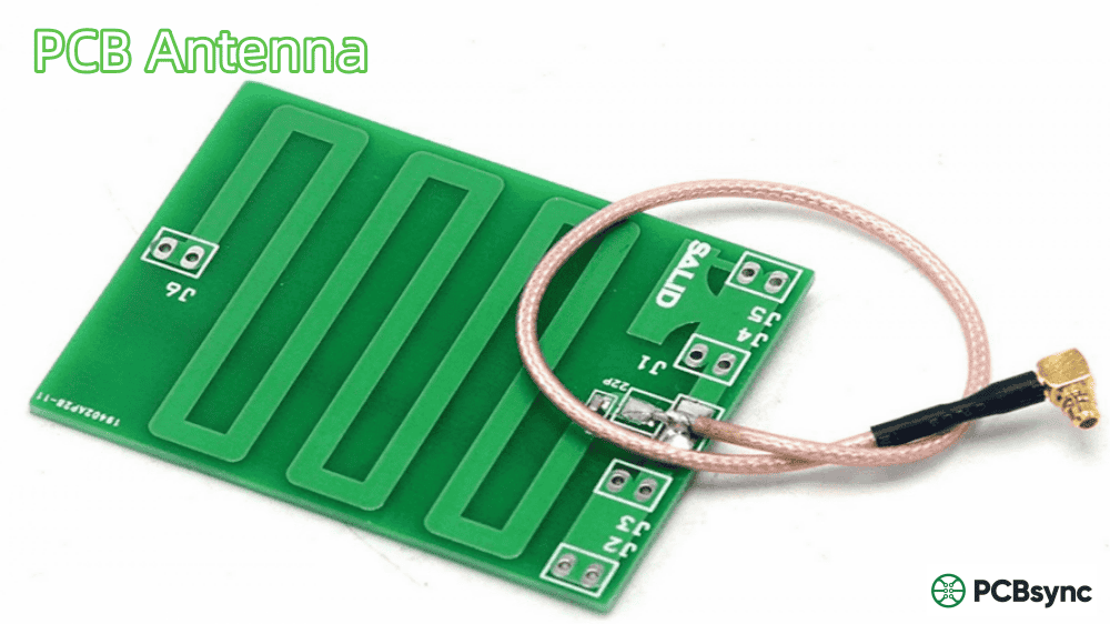
Green printed circuit with meandering copper and a coaxial feed. Physical construction example; frequency and efficiency need test records.

Key distinction: A PCB antenna is a printed radiator or coupling structure; its feed line, return path, board outline and enclosure form part of the RF system.

Explore the design before release

PCB Antenna tools & quotation planning

PCB Antenna project tools

PCBSync Engineering Tools · calculations run in your browser · no account required

Generic RF scenario only — not an antenna performance or named-material quotation. Exact grade pricing, coupons and testing are NOT included. Existing uncalibrated reference model; request a reviewed quotation for the complete project.

Start with your design inputs

Example values are editable. Review the result and assumptions before adding a scenario to your enquiry.

Choose the engineering route

Match the antenna approach to the product

ApproachStart here when you needCritical review
Printed trace / inverted-FCompact wireless board edgeGround, clearance, feed and enclosed tuning
Rectangular patch / arrayDirectional coverage and a defined apertureDielectric height, feed, polarization and pattern
Separate flexible circuitRadiator mounted away from the main PCBAdhesive, bend, cable route and placement tolerance
LF / NFC coilNear-field reader and tag couplingMeasured L, loading, metal and matching network
Broadband radiatorCoverage across a wide frequency rangeBand-edge match, pattern and timing behavior

PCBSync can review the fabrication and assembly scope from your files. Antenna tuning, radiation measurements and regulatory testing are separate project requirements to agree explicitly.

Design tips and manufacturing decisions

PCB Antenna: what to resolve before fabrication

Choose a structure around the product

Compare a printed trace, separate FPC, chip antenna and external antenna using usable clearance, installation position, required coverage and production assembly. A lower component count is useful only if the final product meets its wireless target. Reserve a matching footprint and accessible measurement point before layout is frozen.

Design output: Required band and antenna topology. Record the decision and the open questions before sending the fabrication package.

Turn an RF design into a fabrication brief

Identify the radiating copper separately from the feed line and from ground keep-outs. Specify laminate grade, dielectric spacing, finished copper, solder mask, surface finish and any restricted geometry changes. A 50-ohm feed does not mean that the radiator itself is a 50-ohm transmission line.

Build output: Board / ground outline and keep-outs; Laminate, copper and permitted geometry changes. Keep those requirements in the drawing and RF review record.

Prove the complete assembly

Define the test band, reference plane and required return-loss limit, then measure radiation efficiency, realized gain or the application-level behavior that matters. Repeat measurements with the enclosure, battery and cables installed. A good input match alone cannot prove useful radiated power.

Acceptance output: Enclosure and agreed RF test scope. Agree the method, sample state and evidence required before ordering.

A clearer brief gets a clearer response

Four requirements for this enquiry

01

Required band and antenna topology

02

Board / ground outline and keep-outs

03

Laminate, copper and permitted geometry changes

04

Enclosure and agreed RF test scope

Attach the current fabrication files and drawing revision. Mark open questions, permitted alternatives and requested delivery timing. For assembly, add BOM and placement files. Ask for exceptions and additional test costs to be identified in the response.

Real physical circuits

Physical PCB examples and construction details

These photographs show visible conductor patterns, pads and mechanical features. Confirm material identity, electrical performance and application qualification through approved project records.

Antenna design library

Find your frequency, structure or application

Existing antenna PCB catalog examples

These are existing product-listing names, not verified stock, performance or application approvals. Confirm the actual construction and test records during quotation.

Catalog examples 1–20
Catalog examples 21–40
Catalog examples 41–60
Catalog examples 61–78
Answers for design and procurement

PCB Antenna FAQ

Can this pcb antenna be sized from frequency alone?

A PCB antenna is a printed radiator or coupling structure; its feed line, return path, board outline and enclosure form part of the RF system. Use the calculator for its stated approximation and validate the actual structure.

What should I include in a pcb antenna quotation?

Include required band and antenna topology, board / ground outline and keep-outs, laminate, copper and permitted geometry changes, enclosure and agreed rf test scope, current fabrication files, quantity and desired arrival date. Identify any assembly and testing scope separately.

Do the photographs prove antenna performance?

No. They show physical circuit construction. Frequency coverage, gain, material identity and qualification require the corresponding project and test records.

How do I request an engineering quotation?

Prepare current fabrication files, the proposed stack-up, quantity and requested delivery. Include material and inspection requirements. For controlled-impedance work, add target impedance, signal mode, controlled layers, reference planes and permitted geometry changes. Mark open questions for review. The planner is optional; you can request a quote with the information you have.

References checked 1 October 2026. Historical sources are labeled. Calculations are planning aids. Use current interface requirements, construction-specific models and agreed test procedures for design release.

From requirements to a reviewable quotation

Discuss your PCB Antenna project

Send the construction you want reviewed

If useful, add a planning result and your assumptions to the enquiry. Include the board revision, quantity, requested arrival date and open questions. Ask the quotation to identify the proposed stack-up, exceptions and inspection scope.

Need an NDA or a particular file-transfer arrangement? Contact us before sending files.

Email: [email protected]
Phone: +86-755-23203480

Review your message and attachments before submitting. An enquiry does not place an order.

Drag & Drop Files, Choose Files to Upload You can upload up to 3 files.