Contact Sales & After-Sales Service

Contact & Quotation

  • Inquire: Call 0086-755-23203480, or reach out via the form below/your sales contact to discuss our design, manufacturing, and assembly capabilities.
  • Quote: Email your PCB files to [email protected] (Preferred for large files) or submit online. We will contact you promptly. Please ensure your email is correct.
Drag & Drop Files, Choose Files to Upload You can upload up to 3 files.

Notes:
For PCB fabrication, we require PCB design file in Gerber RS-274X format (most preferred), *.PCB/DDB (Protel, inform your program version) format or *.BRD (Eagle) format. For PCB assembly, we require PCB design file in above mentioned format, drilling file and BOM. Click to download BOM template To avoid file missing, please include all files into one folder and compress it into .zip or .rar format.

PCBSync · Inspection, test & quality planning

PCB E-Test: Electrical Testing Before Assembly

Request bare-board electrical testing against an agreed netlist and test plan. Define continuity, isolation, coverage exceptions and traceable results before committing valuable components to assembly.

Prototype through production · scope and schedule confirmed after file review

Panel of unpopulated green circuit boards showing repeated board outlines, pads and exposed contact areas.
At a glance: Bare-board E-Test addresses conductive-network integrity under specified conditions. It does not verify component values, firmware, product function, every physical feature or long-term reliability.
Prepare a clearer project request

PCB E-Test tools

PCB E-Test workbench

PCBSync Engineering Tools · no account required · calculations run in your browser

Mark what you have prepared

Match the scope to the decision

PCB E-Test: scope, limitations and evidence

Decision / stageWhat to defineEvidence or next action
Design referenceApproved fabrication revision and source netlistRecorded data comparison and resolved differences
ContinuityRequired conductive paths and agreed limitsProgram and measurement basis
IsolationNet relationships, conditions and exclusionsDocumented test coverage
Access routeProbe access, fixture needs and stable supportReviewed testability plan
Result handoverIdentity, failures, retests and exceptionsAgreed lot/board report and release authority
Practical engineering and purchasing guidance

Define the test before approving the result

Start with a controlled design reference

Send the PCB manufacturing package and an independently exported design netlist from the same approved revision. Comparing a CAM-derived connectivity model with the source design helps identify data discrepancies before test programming. Resolve intentional net ties, isolated pads, panel features and any embedded components explicitly.

Testing only against a model reconstructed from the same incorrect manufacturing data can reproduce the mistake. Identify who approves the reference and how discrepancies are handled. KiCad and other CAD systems can export IPC-D-356 data, but file availability alone does not prove that the correct revision and connectivity were supplied.

Specify what continuity and isolation mean for this board

The test plan must define which conductive paths and net relationships are evaluated, with applicable resistance criteria, measurement conditions and exceptions. Do not copy a generic voltage or resistance threshold from a web article into a production order without reviewing the product requirements and test method.

Agree the relevant contractual standard and revision, along with customer requirements. The public IPC-9252B scope describes testing of unpopulated boards and its limitations; it is not a substitute for the current agreed document or a universal recipe. Boards with embedded components or unusual construction need additional engineering review.

Choose the access method around the actual job

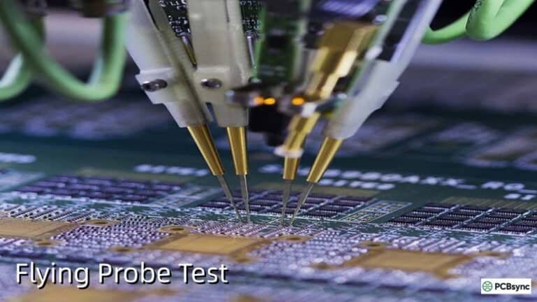
Flying probes avoid a dedicated contact fixture for many designs, while fixture-based routes can reduce repeated contact movement for suitable repeat work. The commercial decision depends on accessibility, board stability, quantity, program effort and the required measurement sequence. Neither route has a universal crossover quantity.

Use the station-time tool with reviewed cycle and handling data to plan one sequential test station. Additional executions are entered assumptions, not a predicted failure rate. Ask the quotation to separate initial data preparation or tooling, recurring test work, exceptional diagnosis and the reporting deliverable.

Preserve evidence through final release

A useful result identifies the board or panel, product revision, approved test program, scope and disposition. Define how a failed contact is distinguished from an actual board defect, how retests are authorized and how the original result is retained. Do not erase the history by reporting only the final passing attempt.

Confirm whether the ordered scope covers each shipped board and which tests occur after final processing. Request the report format, exception handling and release authority in writing. PCBSync can review your files and proposed criteria so the quotation describes the quality evidence your receiving team actually needs.

Keep the review concrete

Include these requirements in your enquiry

01

Fabrication files and source netlist from one revision

02

Intentional net ties and isolated-pad instructions

03

Agreed continuity and isolation criteria

04

Probe access and fixture constraints

05

Quantity, release schedule and repeat-order expectations

06

Traceability, report format and retest policy

Mark unresolved items explicitly. Ask the quotation to identify proposed exceptions, required customer approvals and any inspection or special-process charges that remain open.

See the physical construction

Bare boards, probing and test equipment

The media-library examples distinguish unpopulated boards, test equipment and populated assemblies. Confirm which construction, access method and measurement scope apply to your order; the images do not establish test results.

Browse the supporting pages

PCB E-Test guide library

Answers before requesting a quote

PCB E-Test FAQ

Does E-Test prove the assembled product works?

No. Bare-board electrical testing precedes component assembly. Populated-board measurements and functional verification need their own plans.

Is a Gerber-derived netlist enough?

It can support test programming, but an independent released design netlist enables an additional connectivity comparison. Resolve discrepancies before testing.

Is every board tested?

Specify the ordered coverage and any exceptions in the quotation and quality plan. Do not infer the scope from a generic pass label.

Technical links checked 3 October 2026. Apply the current documentation and project-specific acceptance requirements. Planners do not certify manufacturability or validate uploaded design files.

From planning to a reviewed quotation

Discuss your PCB E-Test requirements

Send the scope you want reviewed

Add your test-scope brief or planning scenario from the tools above. Include the controlled product revision, requested quantity, required timing and open acceptance questions.

Supply the controlled fabrication files relevant to the requested bare-board test, source netlist, revision, quantity, critical circuits and acceptance requirements. Keep these in the PCB documentation package and identify the released netlist the report should reference. Distinguish bare-board continuity/isolation evidence from assembled-board functional acceptance. Confirm confidentiality and file-transfer arrangements before sending proprietary data.

Email: [email protected]
Phone: +86-755-23203480

Review the message and attachments before sending. An enquiry does not place an order.

Drag & Drop Files, Choose Files to Upload You can upload up to 3 files.