Contact Sales & After-Sales Service

Contact & Quotation

  • Inquire: Call 0086-755-23203480, or reach out via the form below/your sales contact to discuss our design, manufacturing, and assembly capabilities.
  • Quote: Email your PCB files to [email protected] (Preferred for large files) or submit online. We will contact you promptly. Please ensure your email is correct.
Drag & Drop Files, Choose Files to Upload You can upload up to 3 files.

Notes:
For PCB fabrication, we require PCB design file in Gerber RS-274X format (most preferred), *.PCB/DDB (Protel, inform your program version) format or *.BRD (Eagle) format. For PCB assembly, we require PCB design file in above mentioned format, drilling file and BOM. Click to download BOM template To avoid file missing, please include all files into one folder and compress it into .zip or .rar format.

PCBSync · Inspection, test & quality planning

PCB Electrical Testing: From Connectivity to Product Behavior

Choose the electrical tests that answer your actual product questions. Separate bare-board connectivity, populated-board measurements and powered functional verification in one clear enquiry.

Prototype through production · scope and schedule confirmed after file review

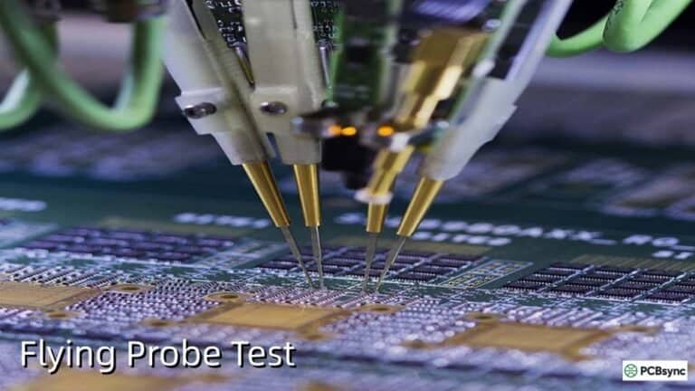
Close view of test probes contacting a populated circuit board.
At a glance: "Electrical testing" describes several different activities. Board construction, test access, excitation conditions and acceptance criteria determine what a result can demonstrate.
Prepare a clearer project request

PCB Electrical Testing tools

PCB Electrical Testing workbench

PCBSync Engineering Tools · no account required · calculations run in your browser

Mark what you have prepared

Match the scope to the decision

PCB Electrical Testing: scope, limitations and evidence

Decision / stageWhat to defineEvidence or next action
Bare boardIntended network connectivitySource netlist and electrical test plan
Populated assemblyAccessible component/network measurementsSchematics, BOM and suitable test access
Powered behaviorInputs, outputs, firmware and operating statesFunctional procedure and expected results
Measurement integrityFixture/contact effects and setup checksControlled setup and verification record
ReleaseCoverage gaps, repairs and final dispositionRequirement-to-result matrix
Practical engineering and purchasing guidance

Define the test before approving the result

State whether the board is populated

An unpopulated board allows a conductive-network test against the intended connectivity. An assembled board contains components and parallel paths that can change the measured response. The same net label does not mean the same test method or acceptance limit can be reused after assembly.

Begin the request with product state and revision. Include schematics, BOM and the relevant design data for a populated PCB assembly. Identify power domains, protection devices and sensitive circuits so engineering can define a suitable test route rather than apply an assumed bare-board procedure.

Assign measurements to specific requirements

A continuity result, resistance measurement, analog signal reading and communication test each answer a different requirement. For every critical objective, specify the expected observation, operating state, applicable limits and disposition of an ambiguous result. Separate circuit access from the measurement capability needed at that access point.

Use the scope-overlap tool only after creating a common requirement list. Two methods may address the same target, so their counts cannot simply be added. The resulting percentage describes your entered coverage map; it is not a measured defect-detection probability or a guarantee that all product risks are controlled.

Plan measurement quality and repeatability

Probe contact, fixture wiring, grounding and the chosen measurement range can influence results. Small resistances may need a reviewed Kelvin arrangement; powered tests may need a defined load, communication partner or external instrument. Keep setup verification distinct from the product acceptance decision.

Define how an unexpected result is investigated before repeated attempts are made. Record equipment and program identities, environmental conditions where relevant and any customer-approved departures. A stable measurement process helps distinguish a real product problem from a fixture or connection problem.

Connect the test route to release evidence

An agreed plan identifies who supplies firmware, fixtures, loads, acceptance limits and expected outputs. It also states which tests are automated, which need operator review and what happens after repair. A concise requirement-to-result matrix is more useful to a buyer than a long list of equipment names.

Send PCBSync the construction state, files, quantity and prioritized requirements for a scoped quotation. Ask for programming or fixture effort, recurring execution, diagnosis and reporting to be identified. Functional validation, environmental evaluation and safety-related verification remain separate scopes unless explicitly included.

Keep the review concrete

Include these requirements in your enquiry

01

Bare or populated construction and revision

02

Schematics and applicable design data

03

Critical electrical requirements

04

Power, load, firmware and interface definitions

05

Measurement setup and fixture responsibilities

06

Traceable reporting and failure disposition

Mark unresolved items explicitly. Ask the quotation to identify proposed exceptions, required customer approvals and any inspection or special-process charges that remain open.

See the physical construction

Bare boards, probing and test equipment

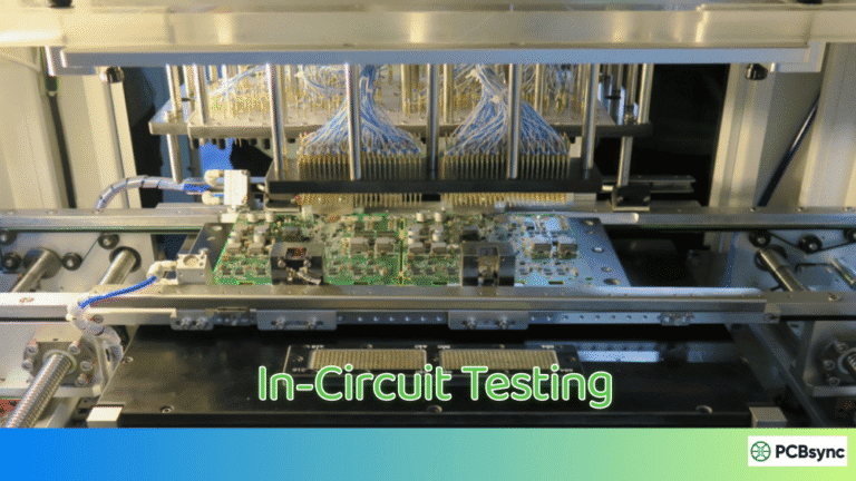
The media-library examples distinguish unpopulated boards, test equipment and populated assemblies. Confirm which construction, access method and measurement scope apply to your order; the images do not establish test results.

Answers before requesting a quote

PCB Electrical Testing FAQ

Does an ICT pass establish complete product function?

Only the checks in the ICT program are demonstrated. Required product behavior needs an appropriate functional test and acceptance definition.

Can the same test fixture be used for every revision?

Review changed geometry, nets, components and limits. Fixture reuse needs a controlled compatibility decision.

Technical links checked 3 October 2026. Apply the current documentation and project-specific acceptance requirements. Planners do not certify manufacturability or validate uploaded design files.

From planning to a reviewed quotation

Discuss your PCB Electrical Testing requirements

Send the scope you want reviewed

Add your test-scope brief or planning scenario from the tools above. Include the controlled product revision, requested quantity, required timing and open acceptance questions.

Supply the controlled files relevant to the requested test, with the source netlist, product revision, critical circuits and acceptance requirements. Identify the stage being tested and the requested report fields in the PCB documentation package. Keep bare-board connectivity, unpowered assembly checks and powered behavior distinct; the ordered evidence should state its coverage and unresolved limits. Confirm confidentiality and transfer arrangements before sharing proprietary data.

Email: [email protected]
Phone: +86-755-23203480

Review the message and attachments before sending. An enquiry does not place an order.

Drag & Drop Files, Choose Files to Upload You can upload up to 3 files.