Inquire: Call 0086-755-23203480, or reach out via the form below/your sales contact to discuss our design, manufacturing, and assembly capabilities.
Quote: Email your PCB files to [email protected] (Preferred for large files) or submit online. We will contact you promptly. Please ensure your email is correct.
Notes: For PCB fabrication, we require PCB design file in Gerber RS-274X format (most preferred), *.PCB/DDB (Protel, inform your program version) format or *.BRD (Eagle) format. For PCB assembly, we require PCB design file in above mentioned format, drilling file and BOM. Click to download BOM template To avoid file missing, please include all files into one folder and compress it into .zip or .rar format.
Flex PCB capabilities: define the construction before the limits
Evaluate your flex circuit as a combination of material, copper pattern, bend geometry, reinforcement and inspection. Use this capability review to prepare the dimensions and tolerances that matter for a project-specific manufacturing assessment.
Drawings reviewed before final price, construction and schedule confirmation.
Branched circuit outline with multiple termination regions.
YOUR NEXT ENGINEERING DECISION
Match the drawing to the manufacturing scope
A capability is meaningful only with its material, copper, stack and tolerance conditions. Use the existing capability information below, then request written confirmation against your drawing revision.
Your notes and supported planner selections stay in this browser tab for two hours. They are not submitted here. Review the summary on Contact before sending an enquiry.
Read the PCBSync quality-control approach. Confirm which inspections and records apply to your drawing, construction and order. A general quality page is not a project-specific acceptance record.
For a comparable quotation, identify the drawing revision, material construction, dimensional requirements, electrical test scope and required shipment records. Discuss document scope and sample availability through Contact.
Describe the feature combination you need. Get a short review agenda before sharing drawings; no files or contact details are required here.
Your next review steps
Supply a local layer map and identify the regions that actually bend. Maximum layer count alone is not a complete requirement.
For connector fit, provide the connector drawing and finished local thickness range. For repeated movement, provide the motion and acceptance conditions. For impedance, identify the nets, stack and required verification.
Keep functional requirements separate from preferences. Ask the review to mark each item accepted, conditional, or unresolved against a drawing revision.
Open detailed calculations and supporting checks
Flex capability review
PCBSync Engineering Tools · prepare a brief, then review and submit it on Contact
Enter your project details, then update the result. Nothing is submitted automatically.
Explore bare-flex cost factors. A price and schedule require file review.
Enter your project details, then update the result. Nothing is submitted automatically.
Use finished thickness in the bend region, including applicable copper, adhesives and coverlay. R/t is a comparison, not a pass/fail rule.
Enter your project details, then update the result. Nothing is submitted automatically.
Design & manufacturing decisions
Flex PCB Capabilities: what to resolve before release
A capability is a combination, not a list of independent extremes
The smallest conductor, thinnest dielectric, largest panel and highest layer count cannot automatically be combined in one build. Finished copper, hole plating, registration, coverlay openings and the size of the production panel all interact. Submit the critical combination you need, including which dimensions are functional and which can be relaxed.
A production-ready capability review should separate a nominal target from a tolerance and a measurement method. For example, connector insertion thickness is not adequately defined by the nominal polyimide thickness. The final local stack includes applicable copper, plating, adhesive and stiffener contributions.
Specify which zones bend and which zones carry components
Provide a region drawing showing the moving flex, fixed interconnect, soldering area and stiffened area. A multilayer product may need different mechanical treatment in each region. The number of copper layers in the bend zone is especially important; it may differ from the maximum count elsewhere in a rigid-flex design.
Do not qualify repeated-motion use by the appearance of a sample. Fatigue depends on the manufactured stack and installed movement. Agree the bend fixture, radius, travel, cycle target and failure criterion before any qualification run.
Define what the inspection package must prove
Electrical continuity testing, dimensional inspection and a connector-fit review address different risks. If controlled impedance is required, identify the nets, target values, tolerance and coupon expectations. If traceability or a specific acceptance class is required, put it in the RFQ and ask for the applicable documentation to be confirmed.
For flexible PCB manufacturing, keep the latest fabrication drawing and approved exceptions with the purchase order. This is the reference for repeat orders, engineering changes and resolving differences between a prototype and a production lot.
Turn a capability question into a controlled decision
Customer requirementDimension, tolerance, operating condition and document revision.
Manufacturing responseAccepted construction, proposed exception or information still needed.
Approval recordNamed drawing revision, accepted exceptions and inspection scope.
A useful capability review begins with the most restrictive combination in the design. If a narrow connector tail also needs plated interconnection, local reinforcement and a controlled insertion thickness, send those features together. Reviewing them separately can hide the interaction that determines whether the design can be built consistently. Mark the dimensions that control fit or function and identify dimensions that can change without changing the product.
A numeric value on a generic capability chart is not sufficient evidence for your particular construction. The same nominal line width can mean different requirements when copper thickness, material, panel geometry and registration change. Ask the quotation to identify the assumed stack and which dimensions apply to finished features. This page prepares that discussion; it does not substitute unverified minimum dimensions for a project review.
Use three response states in the returned drawing: accepted as specified, accepted with a documented exception, and not yet confirmed. A conditional response is useful if it explains the alternative and its effect on fit, electrical behavior or assembly. Do not treat silence as acceptance. Keep unresolved points visible until the customer and manufacturer agree the revision to be manufactured.
For a repeat order, compare the new purchase request with the approved package rather than sending only an old order number. Changes to material grade, outline, connector, assembly or inspection can make an earlier review incomplete. Include the first-build findings and identify any requirement that became critical during installation. This creates a clearer basis for comparing quotations and evaluating the delivered circuits.
Review, acceptance and handoff
Choose inspection evidence that answers the risk, rather than requesting every available report. If connector fit controls the product, define the measurement location and acceptable interval at that interface. If signal impedance matters, identify the relevant nets and the evidence requested for them. If the circuit will move, specify how the motion requirement will be evaluated. A continuity result does not establish mechanical endurance, and a dimensional report does not demonstrate signal performance. Each requirement needs an appropriate acceptance method.
For a first build, distinguish feasibility from production readiness. A prototype can help establish the installed shape and resolve drawing ambiguity without proving that every later production lot will meet the same result. Record which assumptions the first build is intended to test. When reviewing the results, separate a design change from a manufacturing correction so the next revision has a clear purpose. Keep photographs and measurements tied to the particular article and its construction.
Request an exception list in a form that purchasing and engineering can both understand. Each exception should identify the requested feature, the proposed change, the reason and the approval needed. A broad note such as subject to engineering review leaves too much uncertainty if no open questions are attached. Ask the supplier to identify what is still needed to close the review and who must provide it. This makes the quotation a useful decision document.
Do not combine a capability claim with a material availability assumption. A construction may be technically reviewable while its exact laminate or finish requires a separate procurement check. Ask whether an alternative is being proposed, whether it changes the validation plan and whether the schedule depends on material arrival or customer approval. Record the approved alternative explicitly rather than allowing the material family name to conceal a change in grade.
For controlled documents, use an index that includes artwork, fabrication drawing, stack-up, mechanical drawing, assembly information where relevant, and inspection requirements. Give every item a revision or date. If one file changes, identify the affected dimensions and which earlier approval must be revisited. A complete package reduces avoidable questions and makes a repeated order easier to compare with the original agreement. It also helps distinguish missing information from a deliberate design choice.
The next step is a project-specific review, not an order placed by completing a checklist. Use the planner to summarize the critical requirements and send the matching files on Contact. Ask for the construction, exceptions, inspection scope and commercial assumptions to be identified in the response. Approve the reviewed revision through the agreed purchasing process. The checklist is useful because it organizes the conversation; it is not an automatic manufacturability certificate.
Build a clear specification
The details that make a quotation comparable
Decision
What to define
Review focus
Geometry
Outline, smallest features and dimensional tolerance
Dimensioned drawing and copper files
Layer construction
Copper layers, base film, adhesive and coverlay
Proposed stack-up with local regions
Bending
Inside radius, static or moving duty, target cycles
Mechanical motion drawing or fixture concept
Connector region
Contact orientation, thickness range, stiffener position
Connector manufacturer drawing
Verification
Electrical test, dimensional checks, impedance where applicable
Requested test and acceptance plan
Requested features are reviewed as a complete construction. A sample image, calculator result or general material family does not establish a certified capability, tested bend life or approved manufacturing stack-up.
Physical examples
See the construction details
Selected physical circuit photographs from the PCBSync media library. Captions describe visible structures; layer count, material grade and qualification are confirmed from project documentation.
Long flexible interconnects with exposed contact ends.
Flexible circuit with exposed pads and contact fingers.
Close view of a contact tail with local reinforcement.
Flexible tail inserted into a board-mounted connector.
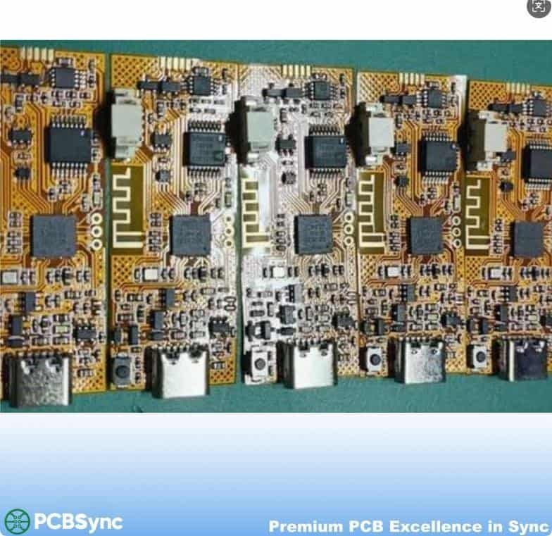
Repeated populated circuit assemblies in a production panel.
Why are blanket minimum dimensions not listed here?
A limit without the associated material, copper, layer construction and tolerance can be misleading. Share your actual feature combination so the manufacturing review can confirm an achievable specification and document exceptions.
Does an IPC class request prove certification?
No. A requested acceptance class is a requirement for review. It does not establish a company certification or guarantee that every design is suitable. Confirm the applicable document, revision and inspection scope in the quotation.
Include the circuit outline and copper data, proposed stack-up, coverlay and stiffener drawings, quantity and required arrival date. Add BOM, placement and assembly files if you need populated circuits.
Describe the installed bend, connector interface and the requirements still open. Ask us to identify construction exceptions, separate optional processes and confirm the schedule with the quotation.
For files requiring an NDA or a specific transfer arrangement, contact us before sending the design.