Contact Sales & After-Sales Service

Contact & Quotation

  • Inquire: Call 0086-755-23203480, or reach out via the form below/your sales contact to discuss our design, manufacturing, and assembly capabilities.
  • Quote: Email your PCB files to [email protected] (Preferred for large files) or submit online. We will contact you promptly. Please ensure your email is correct.

Send your project files and enquiry on Contact →

Notes:
For PCB fabrication, we require PCB design file in Gerber RS-274X format (most preferred), *.PCB/DDB (Protel, inform your program version) format or *.BRD (Eagle) format. For PCB assembly, we require PCB design file in above mentioned format, drilling file and BOM. Click to download BOM template To avoid file missing, please include all files into one folder and compress it into .zip or .rar format.

Flex circuits · engineering & manufacturing

Flexible PCB manufacturing for your design and application

A flexible PCB connects and carries circuitry on a thin, bendable substrate. The right construction depends on what moves, what stays fixed, and how the circuit connects to the rest of your product. Choose a construction, prepare your design requirements and understand the cost drivers before requesting a file-based quotation.

Drawings reviewed before final price, construction and schedule confirmation.

Flexible PCB manufacturing · 61-second process overview.
Find your manufacturing path

From a flexible interconnect to an assembled circuit

Bare flexible circuits

Compare single-sided, double-sided and multilayer constructions around your routing and installed shape.

Review fabrication scope →

Populated flex assemblies

Bring component sourcing, placement, local support and inspection into the same project discussion.

Explore flex assembly →

Rigid-flex alternatives

Compare integrated rigid component regions when separate boards and connectors complicate the product.

Compare rigid-flex →

The quotation confirms the material, dimensions, inspection scope and delivery conditions for your specific files.

YOUR NEXT ENGINEERING DECISION

Choose a manufacturing route

Compare the circuit architecture first. Then resolve material, bend and assembly requirements before requesting a file-based quotation.

Keep a project summary across these guides

Your notes and supported planner selections stay in this browser tab for two hours. They are not submitted here. Review the summary on Contact before sending an enquiry.

Review summary on Contact →

Review quality scope before placing an order

Read the PCBSync quality-control approach. Confirm which inspections and records apply to your drawing, construction and order. A general quality page is not a project-specific acceptance record.

For a comparable quotation, identify the drawing revision, material construction, dimensional requirements, electrical test scope and required shipment records. Discuss document scope and sample availability through Contact.

Files ready? Send your drawing and requirements for a quotation. You do not need to complete every tool first.

Make the next decision

Flex project planner

Start with the design checklist. Explore material requirements, cost drivers and bend geometry, then carry your results to Contact. No files or contact details are required to use these tools.

Flex project planner

PCBSync Engineering Tools · prepare a brief, then review and submit it on Contact

Explore bare-flex cost factors. A price and schedule require file review.

Enter your project details, then update the result. Nothing is submitted automatically.

Design & manufacturing decisions

Flexible PCB: what to resolve before release

Start with the movement, then choose the construction

A circuit folded once during assembly has a different duty from a cable that moves every time a mechanism operates. Mark the bend zone on the mechanical drawing, give the inside bend radius, and describe the full motion rather than simply writing “flexible.” For repeated motion, include target cycles, travel, temperature and the way the ends are restrained. That information determines what needs to be reviewed in the copper, coverlay, adhesive and local reinforcement.

Keep connector loads and solder joints out of the moving area. A thin circuit can still be damaged by a sharp enclosure edge or by a stiffener that ends inside the bend. The photograph of a folded sample demonstrates geometry; it does not establish a tested fatigue life.

Choose the simplest circuit that solves the interconnect

A single-sided flex can be an efficient replacement for a simple wiring path. Double-sided flex adds routing freedom and plated interconnection. Multilayer flex supports more complex routing, but additional bonded layers can make the moving section less compliant. Rigid-flex PCB construction integrates rigid component regions with flex sections and should be evaluated as a different construction, not merely a flex board with a thicker stiffener.

Start with a routing and mechanical sketch before choosing a layer count. Where a dense component area and a moving interconnect coexist, discuss whether a locally reinforced flex, a reduced-layer flex section or a rigid-flex arrangement is the better fit. We review the actual layer map and fabrication files before confirming a build.

Turn an interesting sample into a manufacturable RFQ

A useful quotation package includes copper artwork, board outline, drill data where applicable, a layer stack, coverlay openings and the location of each stiffener. Provide a connector drawing if insertion thickness or contact orientation is critical. For flex PCB assembly, include a BOM, placement file and assembly drawing as well.

Tell us the order quantity and repeat-order expectation separately. State whether dimensions refer to one circuit or a delivery panel. Ask for exceptions to be identified before approval: material substitutions, tooling, panel rails, fixtures, inspection, assembly and freight can change the final price. A reference calculator cannot inspect your Gerber files or reserve a production date.

Build a clear specification

The details that make a quotation comparable

DecisionWhat to defineReview focus
Single-sided flexSimple interconnects and constrained routingOne copper layer; define contact access and local support
Double-sided flexRouting on two copper facesReview plated holes, layer transitions and bend-zone copper
Multilayer flexDenser routing or additional reference layersReview bonded thickness, layer count in each bend and lamination
Rigid-flex alternativeRigid component regions integrated with a flexible interconnectDefine transitions and rigid/flex stack-ups separately
Assembled flexComponents mounted on flexible circuitryAdd carrier, stencil, thermal-process and test requirements

Requested features are reviewed as a complete construction. A sample image, calculator result or general material family does not establish a certified capability, tested bend life or approved manufacturing stack-up.

Materials & construction

Specify the complete stack, not just the film

Base laminate

Specify copper, dielectric and adhesive construction together. Temperature, assembly and movement requirements matter more than a material name alone.

Compare material decisions →

Bend zone

Identify which layers actually bend, the installed radius and whether movement repeats. Qualification needs the real stack and operating conditions.

Review the bend region →

Connector support

Match finished insertion thickness, contact orientation and local support to the connector drawing. Keep stiffener transitions away from moving regions.

Plan local reinforcement →
Agree before production

Make the manufacturing agreement explicit

Construction confirmation

Ask for the reviewed stack, material exceptions and critical dimensions to be identified against a controlled drawing revision.

Prepare a capability review →

Inspection scope

Agree which electrical, dimensional and visual checks apply and what records are required. Bend-life testing needs its own conditions and acceptance criteria.

Discuss quality requirements →

Cost and delivery

Separate circuit quantity, tooling, fixtures, assembly and shipping in the quotation. Confirm material availability and approval dependencies before committing to a date.

Understand quotation drivers →
Physical examples

See the construction details

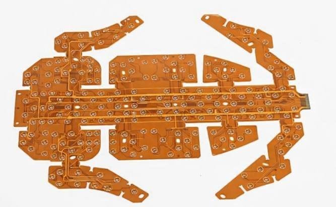
Selected physical circuit photographs from the PCBSync media library. Captions describe visible structures; layer count, material grade and qualification are confirmed from project documentation.

Common project questions

Flexible PCB FAQ

Is a flexible PCB the same as rigid-flex?

No. A flex circuit may include local stiffeners that provide mechanical support. Rigid-flex uses an integrated construction with rigid circuit regions and flexible interconnections. Compare the electrical layer map, assembly support and total system connections before choosing.

Can you quote from a photograph?

A photograph helps explain geometry, but an accurate manufacturing quotation needs artwork and a construction drawing. If your design is still developing, send an outline, approximate size, layer concept and quantity so the missing information can be identified.

Does more copper or more layers improve a flex circuit?

Only when the electrical requirement justifies it. Extra conductor area can help current distribution, while additional layers can improve routing. Both can affect thickness and mechanical behavior, so electrical and bend requirements need to be reviewed together.

Further reading:DuPont laminate families
From concept to a reviewed quote

Discuss your Flexible PCB project

Send the revision you want us to review

Include the circuit outline and copper data, proposed stack-up, coverlay and stiffener drawings, quantity and required arrival date. Add BOM, placement and assembly files if you need populated circuits.

Describe the installed bend, connector interface and the requirements still open. Ask us to identify construction exceptions, separate optional processes and confirm the schedule with the quotation.

For files requiring an NDA or a specific transfer arrangement, contact us before sending the design.

Email: [email protected]
Phone: +86-755-23203480

On Contact, review your carried project brief against the files and your latest inputs. Sending an enquiry does not place a manufacturing order.

What happens after your enquiry?

  1. Review the drawing revision and identify missing information.
  2. Clarify construction, quantity, inspection and delivery requirements.
  3. Review the quotation and agreed scope before ordering.

Ready for the next step?

Send your drawings and requirements through our Contact page. Your enquiry can start with an outline if the design is still developing.

Request a flex PCB quote →