Inquire: Call 0086-755-23203480, or reach out via the form below/your sales contact to discuss our design, manufacturing, and assembly capabilities.
Quote: Email your PCB files to [email protected] (Preferred for large files) or submit online. We will contact you promptly. Please ensure your email is correct.
Notes: For PCB fabrication, we require PCB design file in Gerber RS-274X format (most preferred), *.PCB/DDB (Protel, inform your program version) format or *.BRD (Eagle) format. For PCB assembly, we require PCB design file in above mentioned format, drilling file and BOM. Click to download BOM template To avoid file missing, please include all files into one folder and compress it into .zip or .rar format.
Step Stencil Ordering: Define Step Locations for Mixed-Pitch Assemblies
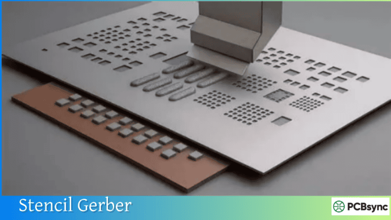
A step-stencil order needs a dimensioned region map, not just a request for “thicker paste at the connector.” Identify the final foil thickness in every region, the face on which the transition is made, the clearance around nearby apertures, and the printer interface. Have the stencil supplier and assembly process owner resolve those items before releasing the cutting data.
This guide is for mixed-pitch assemblies where one paste-printing arrangement must serve different deposition needs. It provides an ordering worksheet and a first-print review sequence. It does not prescribe a universal step height, keepout distance or qualified PCBSync process window.
Illustrative zone map. The colored boundary is a review aid; obtain actual dimensions and clearances from the approved supplier drawing. Open full-size diagram
First decide whether a step is the right solution
Mixed package sizes alone do not prove that a stepped foil is necessary. Start by identifying a specific conflict: a common foil and aperture arrangement cannot deliver acceptable deposits at both a fine-pitch field and a larger joint. Record the affected reference designators and the observed defect or design concern. A heavy component is not automatically a high-paste-volume joint, and component height is not a stencil-thickness selection rule.
ASMPT describes multi-level stencils as one approach to boards with a high component mix. That establishes an available process concept, not a guarantee that a particular layout can use it. Review aperture changes, local thickness changes and separate deposition operations with the process owner. The useful decision is which option can be built, inspected and repeated with the available printer and support arrangement. See ASMPT’s stencil technology overview for the distinctions between single-level, multi-level and other deposition approaches.
Draw the step region in the same coordinate system as the paste data
Supply the released paste file, board or panel outline and assembly reference drawing together. Mark top or bottom print, units, coordinate origin and viewing direction. A screenshot can explain intent, but the supplier needs dimensioned geometry that can be registered to the aperture data. For a bottom-side stencil, agree on the file convention instead of manually mirroring a screenshot and assuming the supplier will interpret it correctly.
Give each proposed region an ID, such as A or B, and list the components it serves. Define the region boundary as a closed shape. Include adjacent openings outside that boundary in the review: a step that clears the intended component can still interfere with printing at its neighbor. Show the nearest aperture-to-transition distances on both sides of the proposed boundary.
Ordering item
What to specify
What must be confirmed
Reference data
Board revision, paste revision, panel revision, print side
Supplier proposal uses the same released data
Region geometry
Zone ID, boundary, origin, units, affected components
No ambiguity in location or orientation
Thickness
Base foil and requested final local thickness
Actual thickness and tolerances at each region
Step construction
Cross-section identifying board and squeegee faces
Transition construction and printable clearances
Equipment interface
Frame, usable print area, fiducials and squeegee travel
Clamping, board support and cleaning compatibility
Release evidence
Marked proposal, change list and named approval owner
Which file is authorized for manufacture
Specify final thickness, not an ambiguous step depth
“Reduce by 30 micrometres” has no complete meaning without a starting foil thickness, and “step up” does not identify which surface changes. Write the base thickness and the final thickness for each zone. Add a section view with the board-contact face and squeegee face labeled. If two supplier processes create the same local thickness using different surface profiles, the printing implications still need review.
Keep requested and confirmed values in separate worksheet columns. This prevents a procurement note from being mistaken for an approved process specification. Do not infer achievable tolerances or minimum distances from a generic article. They depend on the stencil construction, aperture arrangement and printing system.
Indium’s Powder Choice and Stencil Design Guidelines discusses aperture release and the role of area ratio. For a stepped stencil, assess apertures using their local foil thickness. A useful geometry screening result does not replace paste-print trials, particularly close to a transition.
A worked ordering scenario without invented production results
Consider an illustrative board with a fine-pitch IC at U1 and a connector at J1. The process engineer identifies a deposit-volume conflict. The ordering package should not merely color U1 blue and J1 red. It should answer the following questions:
Which U1 and J1 pads are affected, and what evidence motivates a different deposit?
Does U1’s proposed thin region include all its relevant openings, or only a subset?
What happens to R7 and C12 next to the zone boundary?
Can the supplier position the transition with the required clearances?
Will the section preserve the intended board contact and squeegee motion?
Which deposits will be measured during the first-print review?
If the neighboring parts leave insufficient room, record that as an unresolved layout/process issue. Options for discussion include moving the boundary, revising the layout or changing deposition strategy. Do not shrink the clearance on the drawing simply to make the order appear complete.
Original handoff diagram. Blank project-specific values must be agreed with the supplier and assembly process owner. Open full-size diagram
Copy this step-stencil handoff worksheet
Project / PCB revision:
Paste-file names and revision:
Panel drawing / print side / units / origin:
Printer / frame / usable printing area:
Base foil thickness: requested ____ confirmed ____
Zone ID / component references / boundary file:
Final local thickness: requested ____ confirmed ____
Transition face / section drawing:
Nearest openings inside and outside each boundary:
Supplier clearance requirements and exceptions:
Fiducials / squeegee direction / board support:
Approved aperture modifications:
Supplier proposal revision / approval owner / date:
First-print sample identification and review criteria:
Attach one consolidated change list. If the supplier modifies apertures while developing the step layout, record those changes against the original paste data. Keep a copy of the approved proposal with the purchase order so that a replacement stencil can be ordered from the same release, rather than an old email attachment.
Check the first print at and away from the transitions
Verify the delivered stencil identity before setup. Record the board and panel revision, paste product and lot, support arrangement and printer recipe. Inspect deposits in the fine-pitch region, the larger-pad region, and near each transition. Use the project’s agreed SPI or other measurement criteria and retain the actual inspection records. Review both insufficient and excessive deposits, plus bridging, smearing and repeatability across the selected samples.
When a trial fails, preserve the baseline and change one controllable variable at a time where practical. If several conditions change together, record them all. A successful print at one component does not qualify the full panel, and a drawing approval does not demonstrate reflowed joint acceptability. Carry the stencil revision into the PCB assembly record and evaluate downstream results separately.
Editorial source check: October 11, 2026. Original explanatory diagrams and worksheets; no customer inspection results or human engineer approval are represented.
KEEP EXPLORING
Related engineering articles
Continue with practical guides connected to this topic.