Contact Sales & After-Sales Service

Contact & Quotation

  • Inquire: Call 0086-755-23203480, or reach out via the form below/your sales contact to discuss our design, manufacturing, and assembly capabilities.
  • Quote: Email your PCB files to [email protected] (Preferred for large files) or submit online. We will contact you promptly. Please ensure your email is correct.
One place for your enquiry

Continue on Contact

  1. Download the planning worksheet and review the open items.
  2. Send your requirements and available fabrication files on Contact.
  3. Agree the construction, inspection scope and quotation before ordering.
Request a project review →

Need an NDA or a particular file-transfer method? Contact us before sharing confidential files.

Notes:
For PCB fabrication, we require PCB design file in Gerber RS-274X format (most preferred), *.PCB/DDB (Protel, inform your program version) format or *.BRD (Eagle) format. For PCB assembly, we require PCB design file in above mentioned format, drilling file and BOM. Click to download BOM template To avoid file missing, please include all files into one folder and compress it into .zip or .rar format.

A consistent 20/22/24 allocation comparison with constraint-based selection

22 Layer PCB: Compare the Resources Before Choosing the Count

A 22 layer PCB can be a useful middle option when twenty layers leave a documented resource gap and twenty-four add resources the design may not need. The decision should come from routing and power requirements, the mechanical envelope and a proposed fabrication process. Compare complete allocations rather than treating the layer number as a performance grade.

Design decisions · Construction review · Fabrication & assembly planning

20, 22 and 24-layer resource comparisonPlanning illustration: 20, 22 and 24-layer resource comparison. Read the labelled review points below the figure. This is not an approved manufacturing stackup.22 LAYERS / PLANNING CONCEPT20 layersRoles to define22 layersRoles to define24 layersRoles to defineOne requirements baseline
  • Same requirements
  • Usable signal resources
  • Reference resources
  • Not an approved stackup

Planning illustration. Geometry and layer roles require project review; no dimensions or process approval are implied.

20, 22 and 24-layer resource comparison. Engineering illustration; the layer count does not establish a qualified manufacturing process.
Define the project

20 / 22 / 24 Layer Resource Comparator

Configure the board and prepare your design questions. This custom layer count uses an engineering quotation. The tool prepares a specification and decision brief without inventing a price.

Engineering worksheet · no sign-up

20 / 22 / 24-layer comparison

Compare the same design revision and constraint set before adding layers.

Enable JavaScript to use this worksheet. You can also send your requirements through Contact.

Discuss this project →

Inputs stay in this page until you download them. Nothing is submitted automatically. Review the worksheet, then attach it on Contact.

WORKED ENGINEERING EXAMPLE

Keep three proposals on one common baseline

Hypothetical design scenario · Original conceptual diagram · Not a customer case or approved fabrication specification

Keep three proposals on one common baseline. Original conceptual engineering diagram; hypothetical values.0120: routing conflict0222: targeted change0324: extra resources
20: routing conflict · 22: targeted change · 24: extra resources. Diagram is not to scale.

A hypothetical design review compares 20, 22 and 24 layers. The twenty-layer option has a routing conflict; the twenty-two-layer option assigns an additional resource; the twenty-four-layer option offers more space but changes thickness and via geometry. None should win solely because it has the highest count.

Use this in your design review

  1. Freeze outline, interfaces, thickness limits and quantities for the comparison.
  2. Document what each construction resolves and leaves open.
  3. Compare quotation scope, tolerances and verification requirements together.

What to bring to the review

A decision record should identify the chosen tradeoff and the remaining validation work, not merely select the lowest quoted number.

Discuss this construction →
Board specifications, layer concepts & fabrication brief
PCBSync engineering workbench

22 Layer PCB design & cost planner

Plan the board. Compare the construction. Prepare a useful RFQ.

Enable JavaScript for the planner, or use the Contact page. No sign-in or design-file upload is needed to explore the tool.

01 / Your board specification

02 / Electrical structure

Compare the role of each copper layer before committing to a layout. Coloured rows show electrical assignments, not dielectric dimensions or a pressed stackup.

Confirm material grade, copper, dielectric spacing, impedance and tolerance with engineering. Extra layers alone do not guarantee a continuous return path.

Electrical concept

Signal / ground / power · not to scale

Engineering limits and data storage

This tool prepares specifications; it does not inspect files or issue a price, approved stackup, impedance result or delivery commitment. Non-personal specifications may be retained in this browser tab for two hours. Download and review your brief before sending it through Contact.

Fair comparison

Hold the design requirements constant

Compare twenty-, twenty-two- and twenty-four-layer candidates using the same outline, component set, enabled interfaces and electrical constraints. Otherwise a layout with relaxed spacing or a different package can appear to prove that a lower layer count is sufficient when the requirements actually changed.

Write the limiting requirement beside each candidate. It could be an unresolved escape corridor, a reference interruption, a power-path concern or a fixed thickness envelope. Include design effort as well as fabrication scope: a lower-layer option that needs substantial rerouting and validation is a different project choice. The comparison should make those differences visible without assigning an invented universal cost percentage.

  • Use the same reference revision for the component and net list.
  • Separate fixed requirements from options that the team may change.
Count useful roles

Use a role tally before proposing the physical stack

The following arithmetic is illustrative only. It shows how twenty-two layers might add signal capacity to one twenty-layer allocation, while a twenty-four-layer alternative might add reference resources. These are role budgets, not approved layer orders, material builds or performance predictions.

After the tally, map each signal resource to an actual route and its reference. Check power regions individually rather than counting every mixed copper layer as a full plane. A signal layer that cannot be reached through the package escape, or a reference interrupted along the route, should not be treated as usable merely because it appears in the total.

20 / 22 / 24 Layer Resource Comparator

  1. Resource missing from the baseline
  2. Comparison baseline
  3. Evidence for the added pair
  4. Candidate process definitions
  5. Reason for selecting 22 layers

Work through these decisions in the planner. Keep the resulting brief attached to the same project revision.

A review sequence for this 22-layer project. Selections in the tool create your own brief.
Illustrative optionSignal rolesGround rolesPower rolesTotal
A: routing baseline88420
B: added routing resource108422
C: additional reference resource1010424
Demonstrate the gain

Route the region that decides the comparison

Choose the region that is hardest for the baseline design and perform a focused layout trial. Use the same pad and clearance rules in each candidate. Record whether the additional pair reduces detours, removes prohibited reference crossings or makes space for power connections. Include the transitions needed to access the new routing layer.

If twenty-two layers resolves the local constraint, verify that the remainder of the board still meets its requirements. If it does not, identify why before adding another pair. The limiting factor may be via occupancy, package placement or a connector pin field. More copper layers cannot eliminate a geometric blockage that remains present in every proposed layer.

  • Keep screenshots or layout views tied to each candidate revision.
  • Record unresolved rules as open issues instead of treating a nearly routed board as complete.
Compare constructions

Check thickness and process differences alongside the tally

Ask the fabricator to propose a practical construction for each viable allocation. Keep finished thickness, copper weights, materials and via technologies explicit. A twenty-two-layer design with a different drilled-hole strategy is not simply a twenty-layer build with two sheets added.

Separate the effect of layer count from the effect of process choices. Conventional through-hole multilayers and sequential constructions can use the same copper-layer count. The hole structure determines whether subassemblies must be drilled or plated before final lamination. Request that sequence where relevant, then compare it with the routing benefit and the required PCB prototyping evidence.

Decision and quotation

Write the reason twenty-two layers wins

A useful decision record is specific: it names the constraint, identifies the candidate that satisfies it, and lists the tradeoffs accepted. For example, the selected option may create a needed corridor while retaining the permitted mechanical range. Such a record is stronger than saying twenty-two layers is suitable for a particular industry.

Obtain engineering quotations for the viable candidates on matching quantities and acceptance requirements. Include tooling, agreed coupons and inspection reports in the comparison. Preserve the selected stack and layout revisions after approval, and reopen the comparison when a material or hole-family change affects the original reason for choosing twenty-two layers.

  • State what the extra resources accomplish.
  • Attach the selected allocation and the remaining engineering conditions.
From requirements to evidence

Connect the proposed construction to the inspection plan.

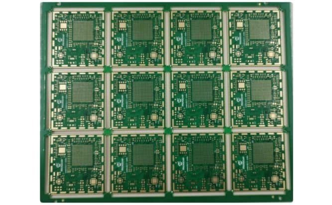
Panelized PCB sample from the PCBSync media library
PCBSync media-library sample illustrating panel format. Project-specific layer count and materials belong in the controlled fabrication record.

What should accompany the quotation?

  • Candidates share one requirements baseline.
  • All role tallies sum to the stated copper-layer count.
  • Added resources have demonstrated routing or power value.
  • Process and quote scopes are comparable.

Match the quoted construction, inspection scope and delivery requirements to the released revision. Confirm what is included before placing an order.

Specific questions

22 Layer PCB questions, answered.

Why choose 22 layers instead of 20 or 24?

Choose twenty-two when its proposed construction satisfies the documented layout and electrical needs with acceptable mechanical and procurement tradeoffs. The right answer depends on usable resources, not a fixed ranking of layer counts.

Are the example role counts a recommended stackup?

No. They are arithmetic examples for comparing resource budgets. Layer order, dielectric gaps, copper thickness, via access and return paths still require a complete engineering review.

Does a 22 layer PCB always need sequential lamination?

No. Layer count alone does not determine the lamination sequence. Blind, buried or build-up interconnect requirements may create separate process steps; the fabricator should define the sequence for the actual structure.

Can adding two layers solve a difficult BGA escape?

Sometimes, if the nets can access useful new routing resources. A blockage caused by the pad field, via geometry or placement may remain. Demonstrate the affected escape region with the proposed rules.

How should procurement compare the three options?

Use the same outline, quantities, materials or approved alternatives, acceptance scope and delivery assumptions. Include the design and validation work each option needs, and request engineering prices for the complete constructions.

Engineering quotation

Request a 22-layer PCB review.

Start with the requirements you know. Include unresolved decisions so engineering can review the construction with you.

  • Candidates share one requirements baseline.
  • All role tallies sum to the stated copper-layer count.
  • Added resources have demonstrated routing or power value.
  • Process and quote scopes are comparable.

Attach fabrication data, the proposed stackup and quantity breaks when ready. For assembly, include the BOM, placement data and inspection requirements.

Discuss NDA arrangements before sharing confidential files. Ask for current certification scope and records relevant to your project.

Contact PCBSync · Include PCB assembly

One place for your enquiry

Continue on Contact

  1. Download the planning worksheet and review the open items.
  2. Send your requirements and available fabrication files on Contact.
  3. Agree the construction, inspection scope and quotation before ordering.
Request a project review →

Need an NDA or a particular file-transfer method? Contact us before sharing confidential files.

Further engineering reading: TTM Technologies: Conventional PCB Manufacturing

PCBSync engineering resources · Updated 1 October 2026 · Planning guidance and illustrations are not approved manufacturing stackups.