Inquire: Call 0086-755-23203480, or reach out via the form below/your sales contact to discuss our design, manufacturing, and assembly capabilities.
Quote: Email your PCB files to [email protected] (Preferred for large files) or submit online. We will contact you promptly. Please ensure your email is correct.
Notes: For PCB fabrication, we require PCB design file in Gerber RS-274X format (most preferred), *.PCB/DDB (Protel, inform your program version) format or *.BRD (Eagle) format. For PCB assembly, we require PCB design file in above mentioned format, drilling file and BOM. Click to download BOM template To avoid file missing, please include all files into one folder and compress it into .zip or .rar format.
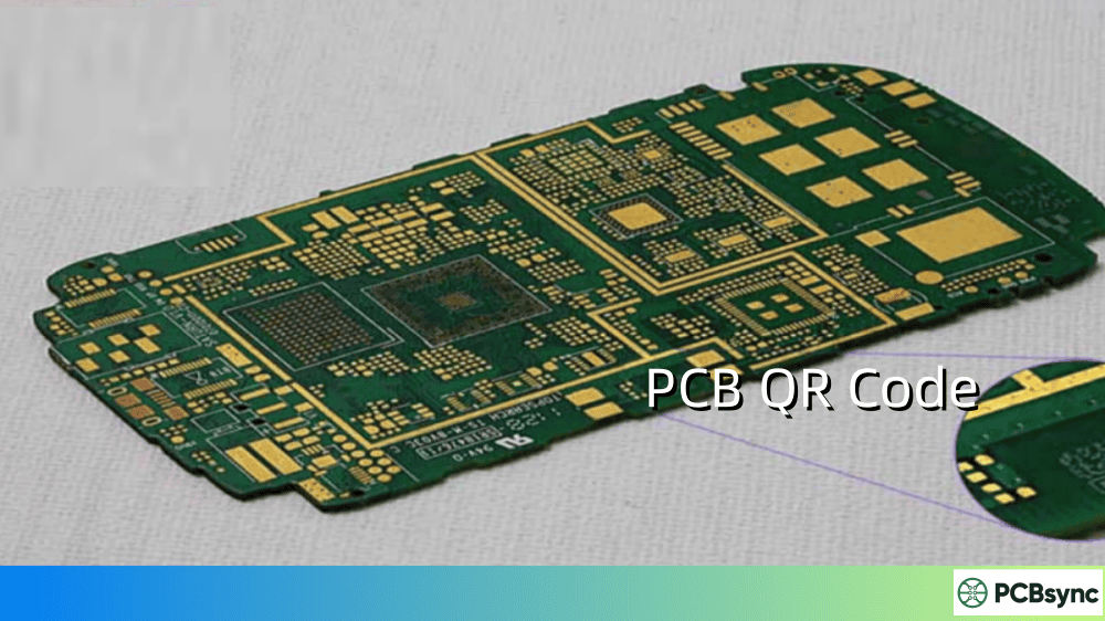
A PCB QR code can connect a physical board to its serial number, build record or controlled documentation. A useful implementation must preserve both readable marking and accurate records through the intended manufacturing and service workflow.
Start by defining the traceability requirement: what must be identified, which records must be retained, and who will read the code. If a customer invokes IPC-1782, agree the applicable revision and traceability scope; placing a QR symbol alone does not demonstrate compliance.
This guide compares QR Code and Data Matrix, explains sizing and marking decisions, and outlines checks for importing a symbol into a PCB design. Validate the final fabrication output and finished marking with the intended reader before production release.
A PCB QR code is a two-dimensional barcode applied to a printed circuit board that stores encoded information. Unlike traditional 1D barcodes that hold limited data in a linear format, QR codes store information both horizontally and vertically, allowing them to pack significantly more data into a smaller footprint.
The “QR” stands for “Quick Response”—and that name isn’t just marketing. These codes were originally developed by Denso Wave in 1994 for tracking automotive parts, and they’ve since become the standard for consumer-facing applications where fast scanning matters.
High data capacity: A single QR code can store up to 4,296 alphanumeric characters or 7,089 numeric digits. That’s enough for serial numbers, URLs, manufacturing dates, and more—all in one compact symbol.
Error correction built-in: Reed-Solomon error correction can recover some damaged data. The commonly quoted L/M/Q/H recovery percentages apply to codewords, not a guaranteed percentage of the printed area that can be covered. Damage to locating patterns can still prevent decoding.
Reader availability: Many smartphones support QR decoding, making it useful for documentation access. Readability still depends on module size, contrast, focus, lighting and the reader implementation.
Rotation tolerance: The QR finder patterns support orientation detection. Rotation tolerance does not guarantee decoding at arbitrary tilt, distance or surface glare.
PCB QR Code vs Data Matrix: Which Should You Use?
Choose the symbol from the required payload, available marking area and reader workflow. QR Code and Data Matrix both support traceability; neither choice by itself defines a compliant manufacturing system.
Comparison Table: QR Code vs Data Matrix for PCB Applications
Decision
QR Code
Data Matrix
Marking area
Derived from symbol version, module size and quiet zone
Derived from symbol format, module size and quiet zone
Quiet zone
For the standard QR symbols discussed here: four modules on each side
For the ECC 200 symbols discussed here: at least one module on each side
Reader workflow
Widely supported for smartphone URL access; validate actual readers
Common in industrial workflows; validate the decoder and data syntax
Payload
Select an encoding/version for the actual data
Select an encoding/format for the actual data
Selection rule
Use when the customer workflow and available area support it
Use when the customer workflow and available area support it
When to Choose QR Codes
Use QR codes when:
End users need to scan the board (linking to documentation, support portals, or firmware)
The application is consumer-facing (IoT devices, maker projects, commercial products)
Smartphone scanning is expected
You can reserve enough area for the selected symbol, its quiet zone and a module size verified with the intended reader
When to Choose Data Matrix
Use Data Matrix when:
Space is limited and the selected payload, marking process and industrial reader support a smaller verified symbol
The code is for internal manufacturing traceability only
The customer or applicable identification specification explicitly selects Data Matrix
ECIA compliance is required for component labeling
For component or regulated-product identification, check the exact customer and sector specification, including data syntax. A requirement for a GS1 symbol on a finished product does not automatically prescribe the marking on every internal PCB.
Getting the size right is critical. Too small and your code won’t scan reliably. Too large and you’re wasting valuable board real estate.
Minimum Size Guidelines for PCB QR Codes
Input
What to establish
Release check
Payload and error correction
Generate the actual symbol and count modules across one side
Keep the payload and chosen encoding under revision control
Module width X
Agree a reproducible module width with the marking process
Check printed module shape and separation
Quiet zone
Reserve four modules on each side of a standard QR symbol
Keep legend, copper features and components out of the clear area
Total area
For N modules per side, reserve (N + 8) × X per side
Verify whether the CAD tool includes or excludes the margin
Reader conditions
Specify reader, lighting, focus and working distance
Test representative finished boards rather than relying on a universal millimetre minimum
Factors That Affect Scanability
Payload length affects symbol density. A shorter controlled URL or identifier can require fewer modules than a long record. Prefer a stable domain and redirect path that your organization maintains; a third-party shortener adds an availability dependency. Retain the complete URI scheme and verify the exact decoded destination.
Error correction is a design input. More redundancy can require a larger symbol version for the same payload. Compare the generated symbol and reserve adequate module size rather than assuming a higher setting will solve poor marking.
Level
Approximate codeword recovery
Decision
L
7%
Evaluate against payload and expected conditions
M
15%
Evaluate against payload and expected conditions
Q
25%
More redundancy may increase required symbol size
H
30%
More redundancy may increase required symbol size
Select the error-correction level with the payload and marking area. Confirm decode performance after the relevant handling and process exposures; no error-correction level guarantees recovery from every damage pattern. See DENSO WAVE’s error-correction explanation.
Quiet zone requirements. For the standard QR symbols discussed here, reserve a clear border four modules wide on every side. For example, a 29-module symbol at an assumed 0.25 mm module width occupies (29 + 8) × 0.25 = 9.25 mm per side including the margin. This is a layout calculation, not a validated minimum size for a PCB process. See DENSO WAVE’s code-area guidance.
PCB QR Code Marking Methods
There are several ways to apply QR codes to PCBs, each with distinct advantages and tradeoffs.
1. Silkscreen Printing
How it works: The QR code is printed during the standard silkscreen process using white epoxy ink over the solder mask.
Pros:
May share an existing legend operation; confirm any added process or inspection cost
Contrast depends on the actual ink, substrate, polarity and reader illumination
Confirm the supplier’s legend method and achievable module reproduction
Cons:
Resolution and edge definition depend on the specific legend process
Can wear over time with handling
A fixed legend image repeats the same code; unique serialization needs a controlled variable-data process
Best for: Static QR codes linking to documentation, company websites, or version information.
2. Laser Marking/Engraving
How it works: A laser changes a qualified marking layer or surface. Select the wavelength and process settings for the actual board materials, and verify readability and substrate condition after the required manufacturing exposures.
Pros:
Can provide a durable direct mark when the substrate and process are qualified
Minimum readable size must be established for the payload, surface and reader
Supports per-board variable identifiers when the marking equipment is connected to a controlled data workflow
Requires process control for fumes, debris and substrate effects
Cons:
Requires specialized equipment
Higher per-unit cost for low volumes
May need white background block for optimal contrast
Best for: Serial numbers, lot codes, and any application requiring unique identification per board.
3. Inkjet Printing (Direct Legend Printing)
How it works: Industrial inkjet printers apply ink directly to the PCB surface, similar to how your home printer works but with specialized UV-curable inks.
Pros:
High resolution and flexibility
Can print variable identifiers when data handling and print verification are controlled
Lower tooling costs than silkscreen
Cons:
Less durable than laser marking
May require protective coating
Quality varies by equipment
Best for: Prototypes, low-volume production, or applications requiring frequent design changes.
4. Polyimide Labels
How it works: A specified label and adhesive system is applied at a defined process stage. Confirm the application method, surface preparation and required exposure resistance with the label supplier.
Pros:
Use a label, adhesive and print system qualified for the actual temperature profile and dwell time
Print resolution must reproduce the selected module size with the chosen label and ribbon or ink
Overall size follows the payload, module width and quiet zone rather than a universal label minimum
Adhesive and removal behavior are product-specific and must suit the traceability requirement
Best for: High-temperature applications, rework scenarios, or when labels need to be applied post-assembly.
How to Add a QR Code in KiCad
KiCad workflows depend on the installed version and available generators. After generation or image conversion, verify the symbol dimensions, layer, polarity and quiet zone in the exported fabrication files.
Click Create a new footprint using the Footprint Wizard
Select “2D Barcode QRCode” from the wizard list
Enter your data (URL, text, etc.)
Set the module width from the agreed marking capability and reader validation
Choose and document the error-correction level for the payload and test conditions
Generate and place the footprint on your board
Method 2: Converting a Prepared Symbol Image
This method works with any image, giving you more control over the source:
Generate the QR symbol with a controlled tool and verify the exact encoded payload
Download as PNG with high resolution
Open Image Converter from the KiCad home screen
Click Load Bitmap and select your QR code image
Set the on-board dimensions from the module count, module width and quiet zone; avoid resampling that distorts the grid
Select Footprint as the Output Format
Choose your board layer (typically Front Silkscreen)
Click Export to Clipboard
In PCB Editor, select Edit → Paste to place the footprint
Move and position as needed
Output check: Keep the full intended URL, including its scheme. Decode the exported artwork and a representative finished mark; do not assume that a reader will repair an incomplete address.
How to Add a QR Code in Altium Designer
Check the barcode functions available in your installed Altium Designer version. The current official workflow uses a configured text object; older versions may require a different supported import method.
Using the Current Documented Barcode Controls
The official Altium barcode instructions describe placing a text object, selecting the BarCode font type and choosing QR Code. Availability depends on the PCB.QRCodes advanced setting. Set module or overall width and margins explicitly, then inspect the fabrication output.
For Versions Without the Required Barcode Controls
If a native generator is unavailable, use an import method documented for the installed version. Preserve square modules, scale and the quiet zone. An arbitrary bitmap or spreadsheet paste is not automatically a valid PCB symbol.
Generate and independently decode the intended payload.
Import through a supported graphics or footprint workflow and confirm physical units.
Check that module geometry, clear margin and chosen layer survive export.
Decode the exported artwork and compare it with the controlled payload.
Confirm the intended production reader, lighting and working distance.
Validate the finished marking with the intended reader before releasing the process.
If an imported symbol consists of many graphic primitives, group them using the version’s supported tools so the pattern and margin remain aligned when moved.
PCB QR Code Placement Guidelines
Where you put the code matters almost as much as the code itself.
Recommended Placement Strategies
Component side (top layer):
Most accessible for scanning during assembly and field service
Higher visibility but competes with components for space
Best for end-user facing products
Non-component side (bottom layer):
Generally more space available
May be obscured in final assembly (enclosures, mounting)
Good for manufacturing traceability that doesn’t need field access
Placement Don’ts
Don’t place over vias – the via holes can disrupt the code pattern
Don’t overlap with laser marking areas – coordinate with your fab house
Don’t place near high-heat components – thermal stress can degrade the marking
Don’t ignore the quiet zone – maintain clear space around the code
Color Contrast Considerations
For best scannability:
Marking arrangement
What to verify
Dark modules on a light background
Use strong contrast and keep the quiet zone the same background color
Light modules on a dark background
This is reverse reflectance; verify that every intended reader supports and reliably decodes it
Colored or glossy surfaces
Evaluate reflectance under the actual reader illumination and viewing geometry
Transparent coating or label overlay
Check glare, distortion and decode performance after application
Polarity matters: White modules on a dark board are a reverse-reflectance symbol, not a universal requirement for dark solder mask. A defined light background with dark modules is another option. Do not invert a symbol solely because of the mask color. Validate the complete mark and readers; see the GS1 color and quality guide.
PCB Traceability with QR Codes: Define the Required Records
For electronics manufacturing traceability, a symbol is an identifier or record locator. If IPC-1782 applies to the project, review the agreed revision and customer requirements separately from symbol design. Readable QR marking alone does not establish traceability compliance.
Traceability Scope to Agree Before Release
Define the material and process records required for this product, their granularity and retention. The checklist below is a project-planning aid, not a reproduction of IPC-1782 levels or an industry-specific compliance assignment.
Decision
Record to agree
Identity granularity
Lot, panel or individual board identifier
Material association
Which material and component lots must be related to that identity
Process association
Which assembly, inspection and test events require records
Access and retention
Record owner, retention period and controlled access
Verification
Check that the physical identifier resolves to the correct record
What to Encode in Your PCB QR Code
Select the required fields or record keys for the agreed traceability scope, for example:
Serial number – Unique identifier for each board
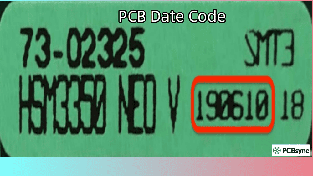
Date code – Manufacturing date (YYWW format typical)
Lot/batch number – Links to material records
Part number and revision – Design identification
Manufacturer code – UL identifier or company code
A URL-based symbol can locate a controlled board or build record, but the destination must remain mapped to the intended identifier. Define that mapping and its revision rules in the PCB documentation package. Include scanning a representative finished board and opening the correct record in first article verification before relying on the same workflow for production. This approach requires controls for the following record changes:
Smaller QR codes (shorter URLs)
Updates to the linked database record without changing the encoded identifier or URL
Extended information access (test results, assembly history, etc.)
Too small: Check module width and reproduction quality; increase the area or simplify the payload, then test again
Poor contrast: Inspect module/background reflectance under the actual illumination
Insufficient quiet zone: Restore four module widths of clear border on every side of a standard QR symbol
URL too long: Use a shorter controlled URL or record key without sacrificing destination stability
Wrong polarity: Confirm the marked polarity is supported by the intended reader; do not assume inversion will fix a contrast problem
Problem: Code Scans But Link Is Broken
Solutions:
Use a maintained redirect under a domain you control; a third-party short URL is not a permanence guarantee
Host QR landing pages on stable domains
Consider encoding static data rather than URLs
Problem: Code Degrades Over Time
Solutions:
Evaluate a qualified direct-marking or label process against the actual service exposures
If a coating is used, qualify its process timing and effects on contrast, glare and readability
Consider more error correction only alongside payload, module size and finished-mark validation
Frequently Asked Questions About PCB QR Codes
What is the minimum size for a PCB QR code?
There is no universal PCB QR minimum in millimetres. Generate the actual payload, select the module width the process and reader can support, and include the required quiet zone. Validate representative finished marks at the intended working distance and after relevant process exposures.
Can QR codes be read on any color solder mask?
Not every ink and solder-mask combination is suitable for every reader. Check module/background reflectance, quiet zone, surface finish and polarity. Reverse-reflectance symbols require reader validation; white solder mask does not automatically require inversion.
What’s the difference between QR code and barcode for PCB marking?
A 1D barcode and a QR symbol use different layouts and decoding methods. Payload capacity depends on the chosen symbology, dimensions and encoding; Code 128 is not universally limited to 20 characters. Choose a format supported by the required reader and identification workflow.
How do I ensure my PCB QR code survives reflow soldering?
Qualify the complete ink, substrate or label-and-adhesive system against the actual reflow profile, dwell time, number of cycles and cleaning process. Laser marking is not automatically unaffected by heat, and polyimide alone does not guarantee a temperature rating. Inspect and decode representative marks after exposure; do not use a coating as an assumed cure for an unqualified marking process.
Should I use dynamic or static QR codes on my PCBs?
The physical symbol always encodes a fixed payload. A so-called dynamic QR service usually encodes a URL whose server-side destination or record can change. Unique serialization is a separate requirement: each board can carry a different fixed serial number or URL, produced through a controlled variable-data process. Laser marking is one possible method, not a prerequisite for a dynamic redirect.
Conclusion
Implementing PCB QR codes starts with the reader workflow and controlled payload. Select the symbol and marking process, reserve module-based dimensions and quiet zone, and verify the exported artwork and finished mark. Keep the identity-to-record relationship under change control.
A readable identifier can support manufacturing records and field service, but it does not by itself prove authenticity or regulatory compliance. Those outcomes depend on the associated controls and evidence.
For an initial deployment, define a small set of required records and a stable identifier format. Test the complete path from marking and scanning to the correct stored record before expanding serialization or traceability scope.
Final Thoughts on PCB QR Code Implementation
For PCB assembly traceability, check that the chosen QR payload maps to the intended board and build record. Verify symbol size, quiet zone and contrast on the finished marking, using the readers and lighting intended for production.
The trend toward greater traceability in electronics manufacturing isn’t slowing down. Whether you’re building IoT devices, medical equipment, or industrial controls, the expectation for traceable, identifiable boards will only increase. Getting comfortable with PCB QR code implementation now positions you well for the evolving requirements of modern manufacturing.
Remember: start simple, test thoroughly, and scale your traceability system as your production needs grow. A well-implemented QR code system isn’t just about compliance—it’s a competitive advantage that improves quality, reduces costs, and builds customer confidence.
KEEP EXPLORING
Related engineering articles
Continue with practical guides connected to this topic.